Home > Products > MV Power Cables

CU/XLPE/CTS(CWS)/PVC Medium Voltage Cable Three Core

CU/XLPE/CTS(CWS)/PVC Medium Voltage Cable Three Core

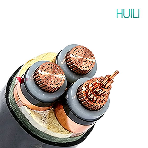
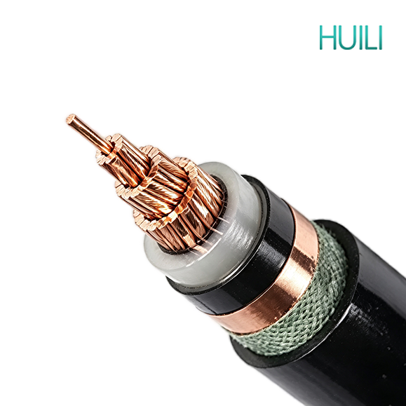
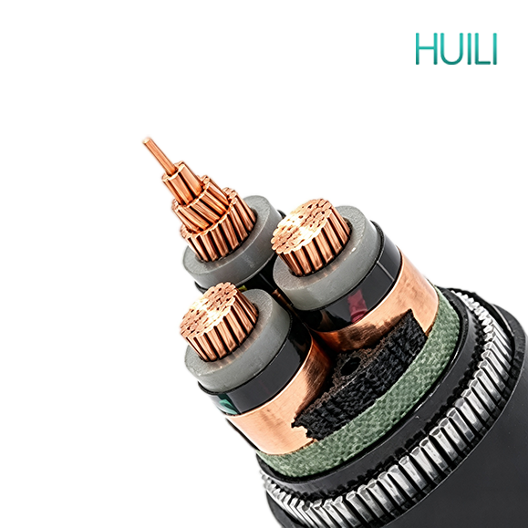
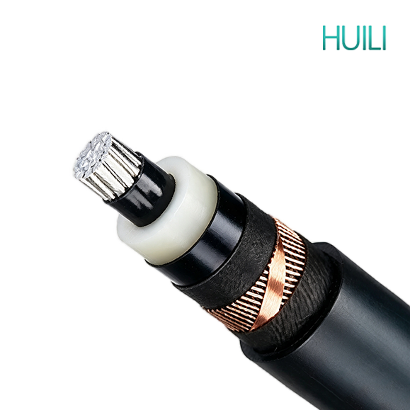
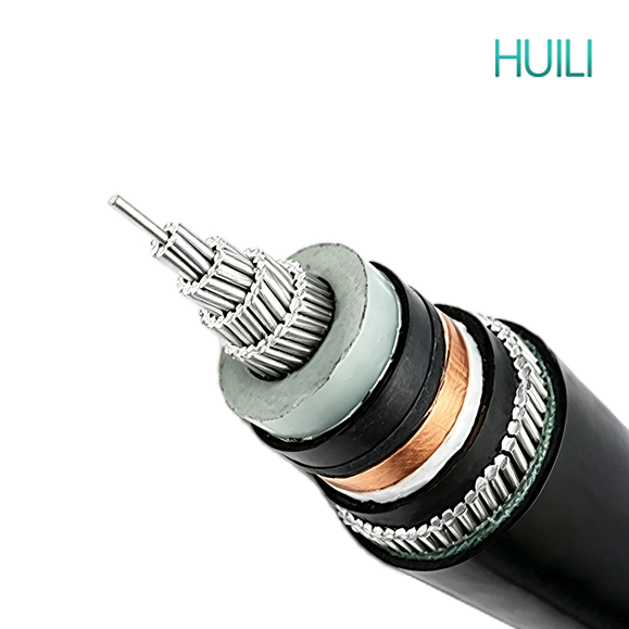
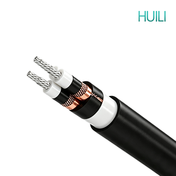
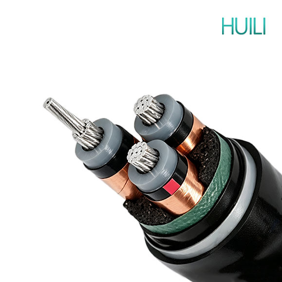
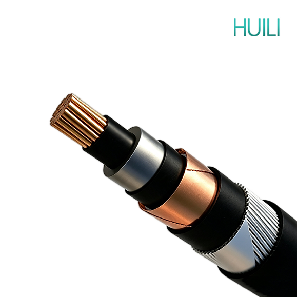
Medium Voltage Cable CU/XLPE/CTS(CWS)/PVC has a stranded copper conductor covered by an extruded XLPE insulation layer.
A copper screen, either tape (CTS) or wire (CWS), is applied over the insulation for field grading and earth fault protection, with an outer PVC sheath for mechanical and moisture protection.

APPLICATION


Widely used in medium-voltage underground power transmission and distribution systems, industrial facilities, substations, and utility networks. Suitable for direct buried, duct, and indoor installations where reliable electrical performance and effective electromagnetic shielding are required.

CONSTRUCTION


f97445c803e3e03db3b17278f0feeda1

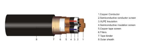
• Conductor: Class 2 stranded circular or circular compacted

• Semi-Conductive Layer for Conductor: Semi-conductive material

• Insulation: XLPE (Cross-Linked Polyethylene)

• Semi-Conductive Layer for Insulation: Semi-conductive material

• Metallic screen: Copper wires / Copper Tape / Copper Wire & Tape

• Outer Sheath: PVC (Polyvinyl Chloride)

CHARACTERISTICS


I. Conductor and Insulation System

1.Conductor: Stranded copper conductor, compacted into a circular or shaped form to minimize air gaps between wires, offering higher conductivity and lower resistive losses than an equivalent aluminum conductor.

2.Conductor Sizing: Cross-sectional area typically ranges from 25mm² to 500mm², allowing smaller conductor sizes to be used for the same current rating compared to aluminum, which can be an advantage in space-constrained duct or conduit runs.

3.Conductor Screen: A semi-conductive compound is extruded directly onto the conductor surface, eliminating any irregularities or air gaps that could otherwise create points of localized electrical stress concentration at the conductor-insulation interface.

4.Main Insulation: Cross-linked polyethylene (XLPE) is applied through a dry-curing process, giving the insulation high dielectric strength, low dielectric loss, and strong resistance to thermal and electrical aging over the cable's service life.

5.Thermal Rating: The conductor is rated for continuous operation at up to 90°C, with a short-circuit temperature tolerance of up to 250°C, allowing the cable to safely absorb transient overload conditions without permanent damage to the insulation.

II. Screening and Fault Current Path

1.Insulation Screen: A second semi-conductive layer is extruded over the insulation surface, working together with the conductor screen to form a symmetrical, well-bonded interface on both sides of the insulation.

2.Metallic Screen: The metallic screen is applied over the insulation screen, either as copper tape (CTS) helically wound with overlap, or as copper wire (CWS) laid longitudinally around the core and held in place with a binder tape.

3.Electric Field Control: Together, these layers keep the electric field distributed evenly through the thickness of the insulation, which reduces partial discharge activity — a slow but cumulative process that would otherwise accelerate insulation aging and shorten cable life.

4.Fault Protection: The metallic screen also provides a clearly defined, low-impedance path for earth fault current, which helps protection relays and switchgear detect and clear faults quickly, limiting damage to the cable and surrounding installation.

III. Lightweight, Unarmored Construction

1.No Armor Layer: Without a steel or aluminum armor layer, this cable is significantly lighter and more flexible than an equivalent armored construction, which reduces overall transport weight and simplifies handling on site.

2.Ideal Use Case: Best suited to installations where mechanical protection is already provided externally — such as cable ducts, trays, conduits, risers, and indoor switchgear rooms — rather than direct burial in open ground.

3.Installation Advantages: The reduced weight and smaller minimum bending radius make the cable easier to pull through tight duct runs and route around obstacles in confined spaces such as substations and equipment rooms.

4.Combined Benefit: Pairing a copper conductor with an unarmored design gives higher current capacity in a lighter, more compact cable, which can be useful where both space and weight are constrained.

IV. Moisture Resistance and Environmental Durability

1.Layered Water Resistance: While XLPE insulation is inherently moisture-resistant on its own, the tightly wound metallic screen combined with the PVC outer sheath adds further barriers that make it harder for water to migrate into the cable core over time.

2.Water Treeing Prevention: This layered protection reduces the risk of water treeing, a slow, moisture-driven degradation process that is one of the leading causes of insulation failure in cables exposed to damp conditions.

3.UV and Weather Resistance: The PVC outer sheath is formulated with UV stabilizers and anti-aging additives, allowing the cable to withstand prolonged exposure in protected outdoor locations, such as duct entries or rooftop equipment runs, without significant cracking or embrittlement.

4.Fire Performance Options: Where local fire codes require it, the outer sheath can be supplied in a flame-retardant (FR) or low-smoke halogen-free (LSZH) formulation, which is commonly specified for installations in tunnels, basements, and other enclosed public spaces.

V. Voltage Range and Service Life

1.Voltage Rating: The cable is available across a wide voltage range, from 3.6/6kV up to 26/35kV, covering the majority of medium voltage distribution networks and industrial power supply requirements.

2.Expected Lifespan: Under normal operating conditions and correct installation practices, cables of this construction are generally expected to provide 30 years or more of reliable service.

3.Maintenance Requirements: The sealed, multi-layer construction means very little maintenance is required once the cable is installed and commissioned, helping to lower total lifecycle costs for the project.

VI. Available Configurations

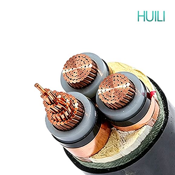
1.Core Configuration: Available in single-core or 3-core versions, depending on the circuit and installation requirements.

2.Screening Options: Choice of copper tape (CTS) or copper wire (CWS) screening, depending on preference and project specification.

3.Application Fit: Particularly well suited to projects where armoring is unnecessary due to protected routing, and where higher current capacity within a lighter, more compact cable is an advantage.

STANDARD


    IEC60502-2;

    IEC60228;

    IEC60332-1/2/3;

    BS6622;

    BS7835;

    DIN VDE 0276-620 ;

    AS/NZS 1429.1;

    GB/T12706;

    ICEA-S-66-524.

    Nominal.Section Conductor dia. Nominal. Insinuation thickness Cable Approx.
    Overall dia.
    mm
    Cable Approx.
    Weight.
    Kg/Km
    Max. D.C.   resistance at 20℃  Ω/KM
    mm2 mm mm Single  core Three core Single  core Three core CU AL
    CU AL CU AL
    10 3.69 2.5 15.3 29.8 324 263 1063 880 1.83 3.08
    16 4.74 2.5 16.3 32.2 401 303 1332 1037 1.15 1.91
    25 6.0  2.5 17.8 35.2 522 366 1717 1247 0.727 1.2
    35.0  7.0  2.5  18.8  37.3  631 416 2069 1419 0.524 0.868
    50.0  8.3  2.5  20.3  40.3  781 489 2543 1663 0.387 0.641
    70.0  10.0  2.5  22.0  44.2  1009 588 3300 2027 0.268 0.443
    95.0  11.6  2.5  23.8  48.0  1291 707 4210 2448 0.193 0.32
    120.0  13.0  2.5  25.2  51.2  1548 810 5054 2825 0.153 0.253
    150.0  14.6  2.5  27.0  54.9  1841 935 5991 3253 0.124 0.206
    185.0  16.2  2.5  28.6  58.5  2215 1076 7206 3766 0.0991 0.164
    240.0  18.4  2.6  31.2  64.1  2804 1311 9108 4596 0.0754 0.125
    300.0  20.6  2.8  34.0  70.1  3435 1568 11155 5515 0.0601 0.1
    400.0  23.5  3.0  37.5  77.6  4320 1920 14021 6771 0.047 0.0778
    500.0  26.6  3.2  41.6  86.6  5460 2374 17754 8431 0.0366 0.0605
    Nominal.Section Conductor dia. Nominal. Insinuation thickness Cable Approx.
    Overall dia.
    mm
    Cable Approx.
    Weight.
    Kg/Km
    Max. D.C.   resistance at 20℃  Ω/KM
    mm2 mm mm Single  core Three core Single  core Three core CU AL
    CU AL CU AL
    16 4.7  3.4 18.3 36.2 468 370 1522 1227 1.15 1.91
    25.0  6.0  3.4  19.6  39.2  585 429 1921 1451 0.727 1.2
    35.0  7.0  3.4  20.8  41.6  706 491 2305 1655 0.524 0.868
    50.0  8.3  3.4  22.1  44.6  851 560 2795 1915 0.387 0.641
    70.0  10.0  3.4  24.0  48.5  1095 673 3572 2298 0.268 0.443
    95.0  11.6  3.4  25.6  52.1  1371 788 4479 2716 0.193 0.32
    120.0  13.0  3.4  27.2  55.3  1644 906 5338 3109 0.153 0.253
    150.0  14.6  3.4  28.8  59.0  1931 1024 6292 3554 0.124 0.206
    185.0  16.2  3.4  30.6  83.8  2323 1184 9847 6408 0.0991 0.164
    240.0  18.4  3.4  33.0  67.8  2910 1417 9413 4900 0.0754 0.125
    300.0  20.6  3.4  35.2  72.9  3510 1643 11390 5750 0.0601 0.1
    400.0  23.5  3.4  38.3  79.5  4377 1977 14176 6926 0.047 0.0778
    500.0  26.6  3.4  42.0  87.5  5496 2410 17783 8460 0.0366 0.0605
    Nominal.Section Conductor dia. Nominal. Insinuation thickness Cable Approx.
    Overall dia.
    mm
    Cable Approx.
    Weight.
    Kg/Km
    Max. D.C.   resistance at 20℃  Ω/KM
    mm2 mm mm Single  core Three core Single  core Three core CU AL
    CU AL CU AL
    25 6.0  4.5  22.0  44.4  672 516 2252 1782 0.727 1.2
    35 7.0  4.5  23.2  46.7  798 583 2648 1998 0.524 0.868
    50 8.3  4.5  24.5  49.7  947 656 3158 2279 0.387 0.641
    70 10.0  4.5  25.9  53.6  1158 737 3962 2689 0.268 0.443
    95 11.6  4.5  26.8  57.2  1454 870 4894 3131 0.193 0.32
    120 13.0  4.5  28.4  60.5  1731 993 5781 3552 0.153 0.253
    150 14.6  4.5  30.8  64.1  2047 1141 6754 4016 0.124 0.206
    185 16.2  4.5  33.0  67.8  1960 822 8017 4578 0.0991 0.164
    240 18.4  4.5  37.0  72.9  3093 1600 9934 5422 0.0754 0.125
    300 20.6  4.5  37.6  77.8  3653 1786 11912 6272 0.0601 0.1
    400 23.5  4.5  40.7  84.7  4530 2130 14785 7535 0.047 0.0778
    500 26.6  4.5  44.4  92.6  5661 2575 18437 9114 0.0366 0.0605
    Nominal.Section Conductor dia. Nominal. Insinuation thickness Cable Approx.
    Overall dia.
    mm
    Cable Approx.
    Weight.
    Kg/Km
    Max. D.C.   resistance at 20℃  Ω/KM
    mm2 mm mm Single  core Three core Single  core Three core CU AL
    CU AL CU AL
    25 6.0  5.5 24.0  48.5 756 601 2549 2079 0.727 1.2
    35 7.0  5.5  25.0  50.8  875 660 2959 2309 0.524 0.868
    50 8.3  5.5  26.5  53.8  1039 748 3488 2608 0.387 0.641
    70 10.0  5.5  28.2  57.7  1284 863 4314 3041 0.268 0.443
    95 11.6  5.5  30.0  61.3  1584 1001 5268 3505 0.193 0.32
    120 13.0  5.5  31.4  64.5  1854 1116 6168 3938 0.153 0.253
    150 14.6  5.5  33.2  68.2  2165 1259 7169 4431 0.124 0.206
    185 16.2  5.5  34.8  72.0  2554 1416 8479 5040 0.0991 0.164
    240 18.4  5.5  37.2  77.0  3157 1664 10403 5891 0.0754 0.125
    300 20.6  5.5  39.6  82.1  3789 1922 12447 6807 0.0601 0.1
    400 23.5  5.5  42.7  88.8  4677 2277 15327 8077 0.047 0.0778
    500 26.6  5.5  46.4  96.7  5821 2735 19026 9704 0.0366 0.0605
    Nominal.Section Conductor dia. Nominal. Insinuation thickness Cable Approx.
    Overall dia.
    mm
    Cable Approx.
    Weight.
    Kg/Km
    Max. D.C.   resistance at 20℃  Ω/KM
    mm2 mm mm Single  core Three core Single  core Three core CU AL
    CU AL CU AL
    25 6.0  8 30.4 62.2 1066 911 3722 3252 0.727 1.2
    35 7.0  8.0  31.4  64.5  1195 980 4178 3528 0.524 0.868
    50 8.3  8.0  32.7  67.5  1361 1070 4766 3886 0.387 0.641
    70 10.0  8.0  34.6  71.4  1637 1216 5669 4396 0.268 0.443
    95 11.6  8.0  36.4  75.1  1956 1373 6701 4939 0.193 0.32
    120 13.0  8.0  37.8  78.3  2240 1502 7665 5436 0.153 0.253
    150 14.6  8.0  39.4  81.9  2553 1647 8730 5992 0.124 0.206
    185 16.2  8.0  41.2  85.6  2976 1837 10088 6649 0.0991 0.164
    240 18.4  8.0  43.6  90.7  3604 2110 12138 7626 0.0754 0.125
    300 20.6  8.0  49.2  95.8  4603 2736 14284 8644 0.0601 0.1
    400 23.5  8.0  49.1  102.5  5180 2780 17296 10046 0.047 0.0778
    500 26.6  8.0  55.6  110.4  6703 3617 21149 11827 0.0366 0.0605
    Nominal.Section Conductor dia. Nominal. Insinuation thickness Cable Approx.
    Overall dia.
    mm
    Cable Approx.
    Weight.
    Kg/Km
    Max. D.C.   resistance at 20℃  Ω/KM
    mm2 mm mm Single  core Three core Single  core Three core CU AL
    CU AL CU AL
    25 6.0  10.5 36.0  74.6 1383 1228 5003 4533 0.727 1.2
    35 7.0  10.5  37.2  77.0  1537 1322 5508 4859 0.524 0.868
    50 8.3  10.5  38.5  80.0  1715 1423 6150 5270 0.387 0.641
    70 10.0  10.5  40.4  83.8  2008 1587 7112 5839 0.268 0.443
    95 11.6  10.5  42.0  87.5  2326 1742 8210 6447 0.193 0.32
    120 13.0  10.5  43.6  90.7  2641 1903 9230 7000 0.153 0.253
    150 14.6  10.5  45.2  94.3  2968 2062 10358 7620 0.124 0.206
    185 16.2  10.5  47.0  98.0  3408 2269 11781 8342 0.0991 0.164
    240 18.4  10.5  49.4  103.1  4058 2564 13923 9410 0.0754 0.125
    300 20.6  10.5  51.6  108.1  4714 2847 16122 10482 0.0601 0.1
    400 23.5  10.5  54.7  114.9  5661 3261 19288 12038 0.047 0.0778
    500 26.6  10.5  58.4  122.9  6875 3789 23293 13970 0.0366 0.0605

    get in touch

    Huili Cable Co., Ltd. (formerly Luohe Huili Cable Co., Ltd. and Luohe Cable Factory) was founded in 1989 and was renamed Huili Cable Co., Ltd. on September 14, 2024. The company's registered capital is RMB 200 million.

      Related Products

      Home WhatsApp Mail Inquiry