CHARACTERISTICS
I. Conductor and Insulation System
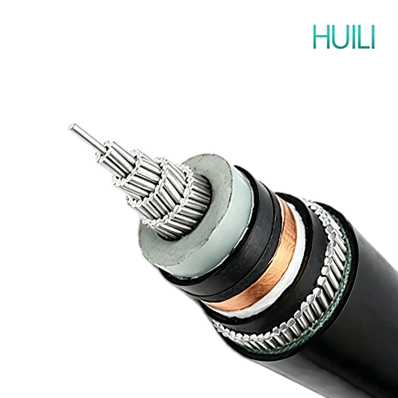
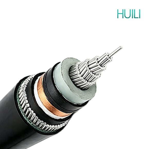
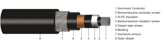
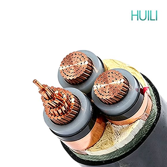
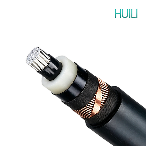
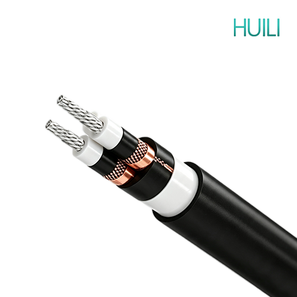
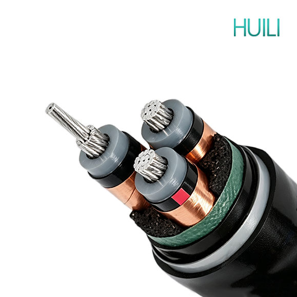
1.Conductor: Stranded aluminum conductor, compacted into a circular or shaped form to minimize air gaps between wires, which improves current distribution and reduces overall conductor diameter compared to a loosely stranded design.
2.Conductor Sizing: Cross-sectional area typically ranges from 25mm² to 500mm², allowing the cable to be matched to a wide range of load and current-carrying requirements, from smaller feeders to higher-capacity distribution circuits.
3.Conductor Screen: A semi-conductive compound is extruded directly onto the conductor surface, eliminating any irregularities or air gaps that could otherwise create points of localized electrical stress concentration at the conductor-insulation interface.
4.Main Insulation: Cross-linked polyethylene (XLPE) is applied through a dry-curing process, giving the insulation high dielectric strength, low dielectric loss, and strong resistance to thermal and electrical aging over the cable's service life.
5.Thermal Rating: The conductor is rated for continuous operation at up to 90°C, with a short-circuit temperature tolerance of up to 250°C, allowing the cable to safely absorb transient overload conditions without permanent damage to the insulation.
II. Screening and Fault Current Path
1.Insulation Screen: A second semi-conductive layer is extruded over the insulation surface, working together with the conductor screen to form a symmetrical, well-bonded interface on both sides of the insulation.
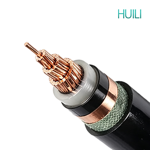
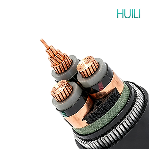
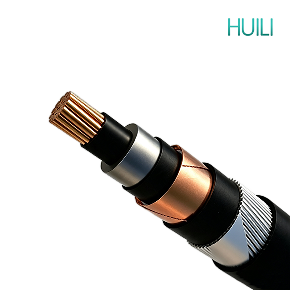
2.Metallic Screen: The metallic screen is applied over the insulation screen, either as copper tape (CTS) helically wound with overlap, or as copper wire (CWS) laid longitudinally around the core and held in place with a binder tape.
3.Electric Field Control: Together, these layers keep the electric field distributed evenly through the thickness of the insulation, which reduces partial discharge activity — a slow but cumulative process that would otherwise accelerate insulation aging and shorten cable life.
4.Fault Protection: The metallic screen also provides a clearly defined, low-impedance path for earth fault current, which helps protection relays and switchgear detect and clear faults quickly, limiting damage to the cable and surrounding installation.
III. Armor and Mechanical Protection
1.Aluminum Wire Armor (AWA): Applied helically over the bedding layer, providing solid resistance to crushing, impact, and accidental damage during installation and backfilling, while being noticeably lighter than an equivalent steel armor construction.
2.Non-Magnetic Advantage: Because aluminum is non-magnetic, AWA avoids the eddy current and hysteresis losses that steel armor can introduce in single-core AC cables, making it a preferred choice for single-core circuits carrying high current.
3.Weight and Handling Benefits: The reduced weight compared to steel wire or steel tape armor makes the cable easier to transport, handle, and pull through ducts, and can lower installation costs on long runs.
4.Rodent and Impact Protection: The armor layer still provides a solid physical barrier against rodents, termites, and everyday site hazards such as sharp stones, careless excavation, or dropped tools during backfilling and compaction.
5.Bending Flexibility: The minimum bending radius is typically 10 to 15 times the overall cable diameter, providing enough flexibility for routing around bends, into trenches, and through duct entries without stressing the internal layers.
IV. Moisture Resistance and Environmental Durability
1.Layered Water Resistance: While XLPE insulation is inherently moisture-resistant on its own, the tightly wound metallic screen combined with the PVC bedding and outer sheath adds several additional barriers that make it much harder for water to migrate into the cable core over time.
2.Water Treeing Prevention: This layered protection significantly reduces the risk of water treeing, a slow, moisture-driven degradation process that is one of the leading causes of insulation failure in buried medium voltage cables.
3.UV and Weather Resistance: The PVC outer sheath is formulated with UV stabilizers and anti-aging additives, so sections of cable that run above ground — such as at riser terminations or equipment connections — resist cracking and embrittlement from prolonged sun exposure.
4.Fire Performance Options: Where local fire codes require it, the outer sheath can be supplied in a flame-retardant (FR) or low-smoke halogen-free (LSZH) formulation, which is commonly specified for installations in tunnels, basements, and other enclosed public spaces.
V. Voltage Range and Service Life
1.Voltage Rating: The cable is available across a wide voltage range, from 3.6/6kV up to 26/35kV, covering the majority of medium voltage distribution networks and industrial power supply requirements.
2.Expected Lifespan: Under normal operating conditions and correct installation practices, cables of this construction are generally expected to provide 30 years or more of reliable service.
3.Maintenance Requirements: The sealed, multi-layer construction means very little maintenance is required once the cable is installed and commissioned, helping to lower total lifecycle costs for the project.
VI. Available Configurations
1.Core Configuration: Available in single-core or 3-core versions, depending on the circuit and installation requirements.
2.Screening Options: Choice of copper tape (CTS) or copper wire (CWS) screening, depending on preference and project specification.
3.Application Fit: AWA construction is particularly well suited to projects where reduced cable weight and non-magnetic performance in single-core runs are priorities.