Home > Products > Cable Accessories

Line Fittings -Tension Clamp,Suspension Clamp,Vibration Damper,Other Clamps

Line Fittings -Tension Clamp,Suspension Clamp,Vibration Damper,Other Clamps

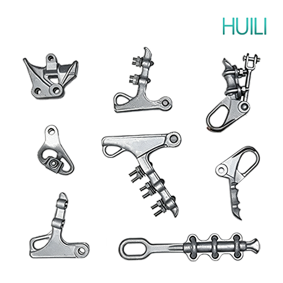
Overhead conductor fittings are metal components used in power transmission lines to fix and clamp conductors and ground wires, enabling connections, splicing, and shock protection. They are high-strength and weather-resistant, ensuring the stable and safe operation of overhead lines.

APPLICATION

Overhead conductor fittings are widely used in high-voltage and ultra-high-voltage transmission lines and distribution network overhead conductor projects. They are mainly used for clamping, splicing, suspending, fixing, tension adjustment, and shock protection of conductors and lightning protection wires. They are compatible with various overhead conductors such as steel-cored aluminum stranded wire and aluminum alloy conductors. They can be installed on straight-line towers and tension towers, used in conjunction with insulators to complete conductor installation, and are also equipped with vibration damping fittings to suppress wind-induced wear on the conductors. The products are resistant to atmospheric corrosion, have strong mechanical load-bearing capacity, and are suitable for various outdoor environments such as mountains, plains, and coastal areas, ensuring long-term safe and stable power transmission of overhead lines.

CONSTRUCTION

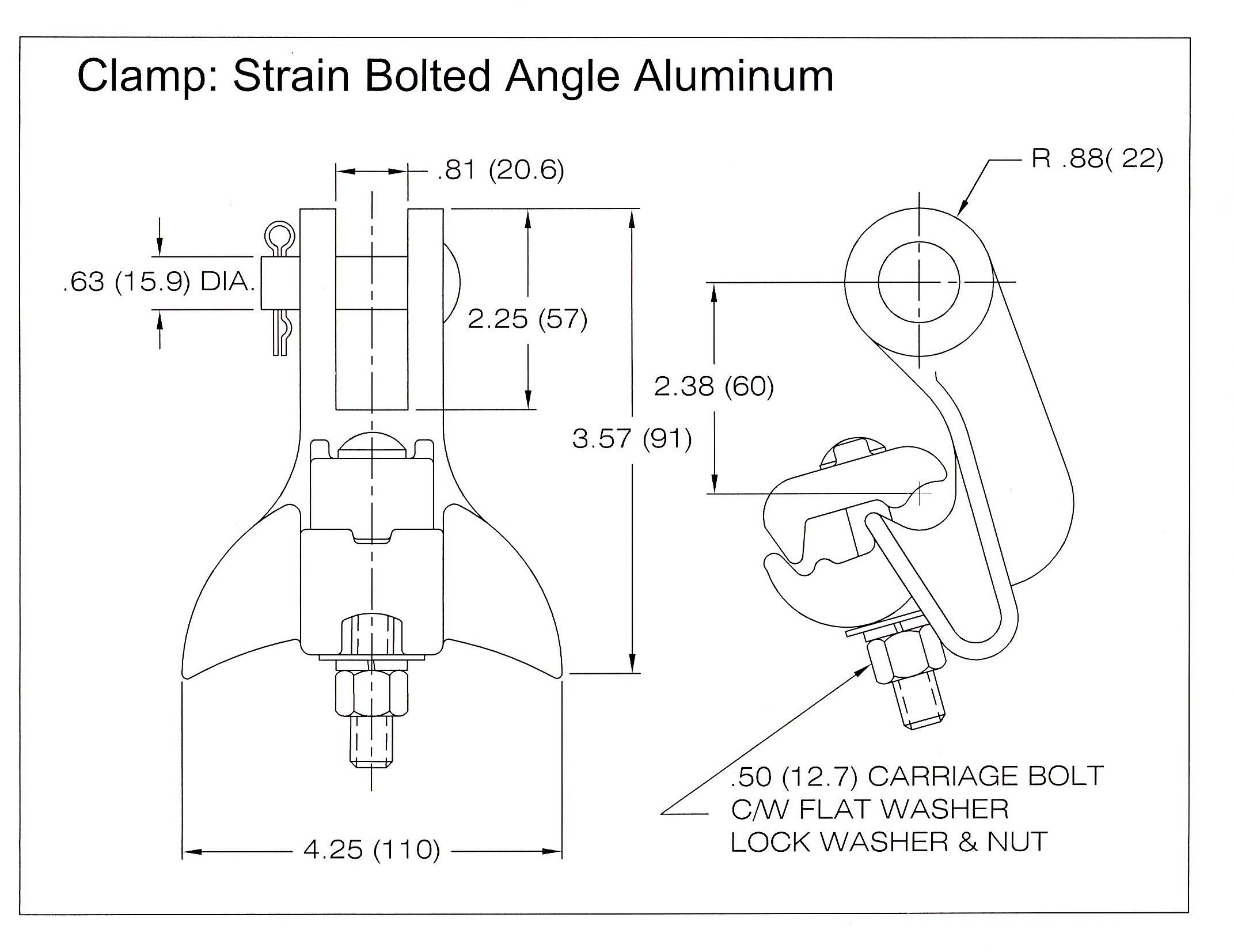
HDA0001373564880000011 PAGE 14 Clamp Strain Bolted

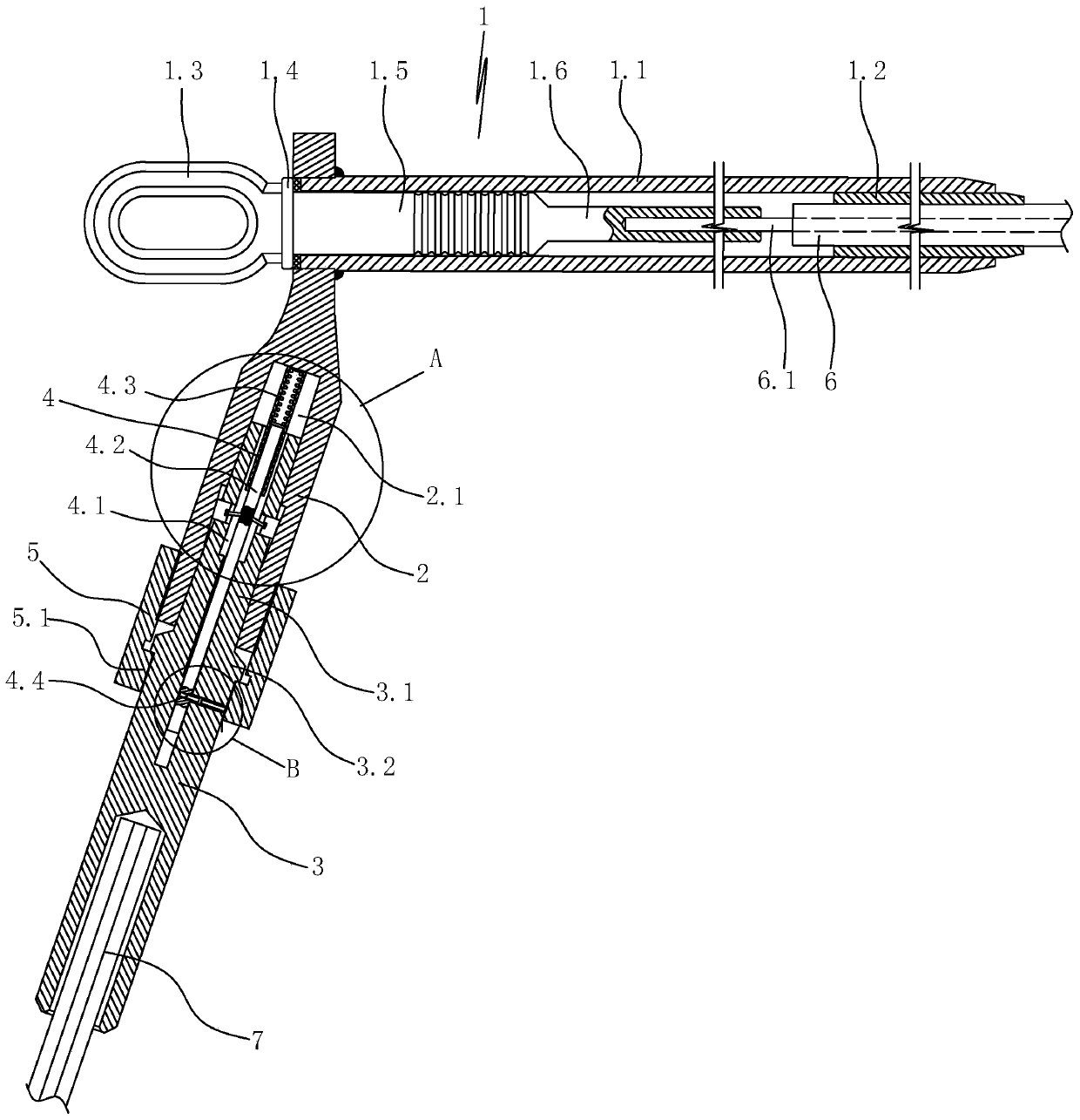
• Tension Clamp

• Suspension Clamp

• Vibration Damper

• Preformed Dead End

• Armor Rods

CHARACTERISTICS

I. Mechanical Characteristics

1. Tension clamp gripping force ≥ 90% of the conductor's rated breaking force; suspension clamp ≥ 15% of the conductor's UTS (Unstable Tense Stretch), safety factor ≥ 2.5;

2. Clamping slot curvature radius ≥ 8 times the conductor's outer diameter; smooth contact surface without sharp corners to avoid damaging aluminum strands and steel core.

3. High tensile/bending strength, capable of withstanding composite loads. Can withstand the conductor's own weight, wind load, icing tension, and conductor swaying impact for extended periods; tension fittings withstand the horizontal tension of the entire conductor, while suspension fittings withstand vertical loads.

4. Movable hinge structure, stress relief. Suspension clamps can swing and deflect with the conductor (maximum swing angle 45°) without generating additional bending stress; connecting plates and hanging rings use ball-and-socket and U-shaped hinges for even force distribution and no jamming.

5. Anti-loosening locking structure. Equipped with anti-loosening bolts, closed pins, and spring washers, ensuring no loosening or detachment under long-term outdoor vibration. Tension Clamps

II. Electrical Performance Characteristics (Core of Conductivity and Safety)

1. Low Contact Resistance, No Heat Generation: Overall resistance of the fitting is ≤ 1.1 times that of the conductor of the same length; the contact surface of the splice/clamp is flat, and conductive grease can be applied to remove the oxide layer; the operating temperature rise does not exceed that of the conductor itself.

2. Matching Conductor Material to Avoid Electrochemical Corrosion

1. Aluminum conductors are fitted with aluminum alloy clamps; hot-dip galvanized steel fittings are used for steel strand ground wires; copper-aluminum transitions use copper-aluminum composite clamps to prevent direct contact between different metals and electrochemical corrosion.

3. High-Voltage Corona Suppression Structure: Ultra-high voltage lines are equipped with equalizing rings and shielding rings; the fitting ends are made with horn-shaped rounded transitions to eliminate corona discharge at the tips and reduce radio interference.

4. Current Carrying Capacity Matched to Conductor: The conductive cross-section and contact area meet the rated current carrying capacity of the conductor, preventing local overheating and conductor burnout.

III. Materials and Corrosion/Weather Resistance Characteristics (Long Outdoor Lifespan)

1. Conductor Clamping Components: Cast aluminum alloy, forged aluminum, lightweight, high conductivity, low magnetic loss;

2. Load-bearing Connectors (Hanging Rings, Connecting Plates, Bolts): Hot-dip galvanized carbon steel, malleable cast iron, high strength;

3. Pre-stretched Wire: Aluminum alloy wire, highly elastic protective wire.

IV. Protective Structure Characteristics (Protecting Conductors from Damage)

1. Flexible Buffer Clamping: Aluminum tape can be used in the bare conductor clamping area; overhead insulated clamps have built-in rubber pads, preventing direct compression of the insulation layer by the hard metal.

2. Matching Vibration Damping and Protection Structure: Equipped with vibration dampers, pre-stretched wire protective wires, and spacers to suppress wind vibration and secondary span oscillation, preventing conductor fatigue and strand breakage.

3. Smooth Transition at the Outlet: Flared ends on the clamps and splice tubes eliminate stress concentration points and prevent conductor bending fatigue fracture.

V. Structural and Installation Adaptability Features

1. Standardized and Modular, Highly Versatile: Divided into six categories: suspension, tension, splicing, connection, protection, and guy wire. Hardware dimensions are uniform for conductors of the same specification, adaptable to corresponding cross-section aluminum stranded wire/steel-cored aluminum stranded wire.

Convenient Installation, High-Altitude Construction Friendly: Available in bolt-type, pre-stranded type, and hydraulic crimp type; pre-stranded wire requires no tools and is quick to assemble and disassemble; crimped connection offers high strength and is suitable for large cross-section conductors.

STANDARD

IEC 61284

IEC 60120

IEC 61466-1

IEEE C135.100

IEEE C135.33

ASTM B500/B500M

Item No. Wire  range(mm²) Dimensions(mm) Grip
Strength
(KN)
Weight
(Kg)
D1 D2 D3 L1 L2 R3 L3
NY-240/30.1 LGJ-240/30 36  16  18  490  65  10  240  72  2.9 
NY-240/40.1 LGJ-240/40 36  16  18  490  65  10  240  79  3.1 
NY-240/55.1 LGJ-240/55 36  20  18  520  65  11  250  97  3.2 
NY-300/15.1 LGJ-300/15 40  14  16  481  61  11  265  65  3.6 
NY-300/20.1 LGJ-300/20 40  14  18  497  67  11  265  72  3.6 
NY-300/25.1 LGJ-300/25 40  14  18  502  67  11  265  79  3.5 
NY-300/40.1 LGJ-300/40 40  16  18  522  67  11  265  88  3.5 
NY-300/50.1 LGJ-300/50 40  18  18  542  77  12  265  98  3.9 
NY-300/70.1 LGJ-300/70 42  22  20  577  82  12  265  122  4.5 
NY-400/20.1 LGJ-400/20 45  14  18  528  68  13  280  84  4.3 
NY-400/25.1 LGJ-400/25 45  14  18  538  68  13  280  91  4.3 
NY-400/40.1 LGJ-400/35 45  16  20  563  78  13  280  99  4.6 
NY-400/50.1 LGJ-400/50 45  20  20  573  78  13  280  117  4.7 
NY-400/65.1 LGJ-400/65 48  22  22  598  83  13  280  123  5.4 
NY-400/95.1 LGJ-400/95 48  26  26  650  95  15  280  163  7.1 


Item No. Applicable conductor
(mm)
     Dimensions(mm) Failure load
(kN)
Weight
(kg)
Bolt size
L I C d
NLL-1 5.1-11.4 135  102  17  16  40kN 0.75  2×M12
NLL-2 11.4-16 155  113  21  16  70kN 0.9  2×M12
NLL-3S 14.5-17.5 170  150  24  16  70KN 1.43  3×M12
NLL-3 14.5-17.5 245  190  30  18  70KN 2.37  3×M14
NLL-4S 18-22.4 227  170  31  16  90KN 2.65  4×M14
NLL-4 18-22.4 280  245  31  18  90KN 3.18  4×M14
NLL-5 23-30 350  235  38  20  120KN 4.5  5×M16
Item No. Wire Rnage Dimension(mm) Ulitmate
(mm) H L R
XGU-1 5.0~7.0 82.5  180  4  40 
XGU-2 7.1~3.0 82  200  7  40 
XGU-3 13.1~21.0 101  220  11  40 
XGU-4 21.1~26.0 109  250  13.5  40 
Item No. Applicable
Conductor
Dimensions(mm) Specification Weight (kg) Specification
a h L1 L
FDZ-1 7.0-12.0 50  66  120  320  19/1.8 0.7  1.8 
FDZ-2 11.0-15.0 50  66  130  350  19/1.8 0.9  2.3 
FDZ-3 14.0-19.0 60  66  150  430  19/2.2 1.7  4.4 
FDZ-4 18.0-22.5 60  66  160  470  19/2.2 2.1  5.5 
FDZ-5F 22.0-29.0 60  95  180  520  19/2.6 3  7.1 
FDZ-6F 28.0-35.0 60  95  180  520  19/2.6 3.6  8.3 
FDZ-1T 7.8  60  30.7  120  320  19/1.8 0.7  1.8 
FDZ-2T 9.0-9.6 60  30.7  130  350  19/1.8 0.9  2.3 
FDZ-3T 11.0-11.5 60  44.7  150  430  19/2.2 1.7  4.4 
FDZ-4T 13  60  44.7  160  470  19/2.2 2.1  5.5 

get in touch

Huili Cable Co., Ltd. (formerly Luohe Huili Cable Co., Ltd. and Luohe Cable Factory) was founded in 1989 and was renamed Huili Cable Co., Ltd. on September 14, 2024. The company's registered capital is RMB 200 million.

    Home WhatsApp Mail Inquiry