Home > Products > Control Cables

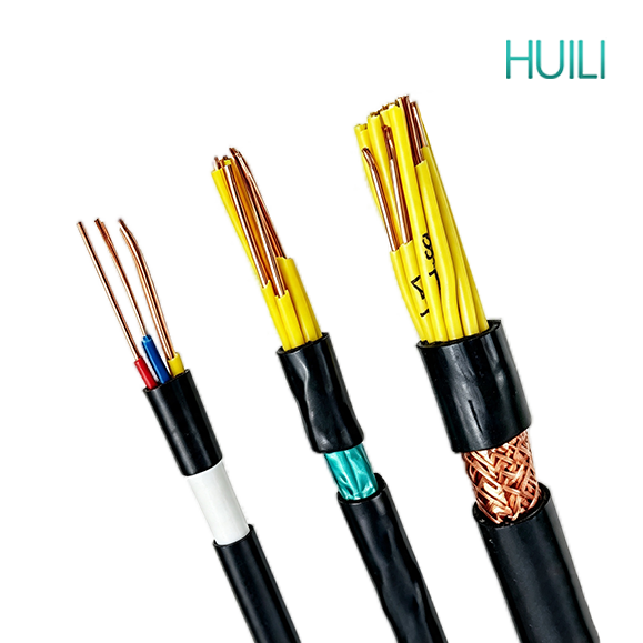
Control Cable NYY PVC Insulated-CU/PVC/PVC- Cable

Control Cable NYY PVC Insulated-CU/PVC/PVC- Cable

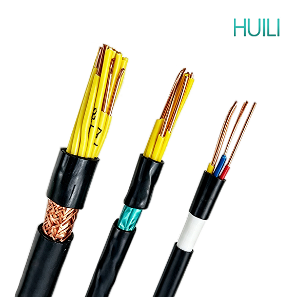
Control cables transmit control and measuring signals rather than heavy power. They are widely used in power stations, substations, industrial automation, fire protection, buildings, new energy and municipal projects. Various types with shielding, fire resistance, flexibility and armor are available to fit indoor, outdoor, buried and harsh industrial installation environments.

APPLICATION


Control cables are designed to transmit control commands, measurement signals and interlock signals instead of high-power electricity, widely applied across multiple industries. In power systems including substations, power plants, photovoltaic and wind energy stations, they connect high & low voltage switchgears, realize breaker remote operation, relay protection and data collection of transformers. 

CONSTRUCTION


e1f94a173c265a3090cddda74c5d2816


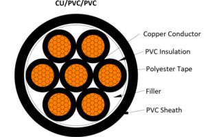
• Conductor: Conductor: Copper, class 1, 2, or 5, solid, stranded round or soft conductor

• Insulation: Polyvinyl chloride PVC

• Filler: Non-hygroscopic material

• Binder: Non-hygroscopic material

• Outer sheath: Polyvinyl chloride PVC

• Rated Voltage:300/500V, 450/750V, 0.6/1kV

CHRACTERISTICS


Core Features of Polyvinyl Chloride (PVC) Insulated Control Cables (KVV/KVVP, etc.)

I. Basic Structure Definition
Conductor: Copper core; Insulation: PVC (Polyvinyl Chloride); Sheath: PVC; Primarily used for instrumentation, control cabinets, and secondary circuit signal/control transmission.

II. Advantages

1. Processing and Laying Advantages
Good flexibility, easy to bend and install
PVC material is soft and does not easily crack when bent, suitable for narrow wiring inside cabinets, cable tray bends, and wiring for frequently moved equipment.

Balanced Mechanical Protection
The outer PVC sheath is wear-resistant, resistant to slight compression, and resistant to minor scratches, sufficient for normal environments in indoor cable trays, trenches, and control cabinets.

Stable Insulation Performance
Power frequency insulation strength meets standards, can withstand 0.6/1kV rated voltage, meeting the insulation requirements of low-voltage control circuits; not prone to leakage, providing basic protection against daily power frequency interference.

Acid and Alkali Resistance, Corrosion Resistance
Has a certain degree of resistance to dilute acids, dilute alkalis, salt spray, and oil stains, suitable for chemical plants, water treatment plants, and mildly corrosive environments in underground cable trenches. Moisture-proof and Waterproof: PVC does not absorb water, making it less susceptible to moisture damage in damp basements and trenches, eliminating the need for additional waterproofing.

Low Cost and High Cost-Effectiveness: PVC raw material is mass-produced and mature, with prices 30%~60% lower than cross-linked polyethylene (YJV), rubber, and fluoroplastic cables, making it the preferred choice for large-scale projects.

Flame Retardant Options Available, Ensuring Basic Safety: ZR-KVV flame-retardant type can be produced, delaying flame spread and reducing fire escalation; available in A/B/C flame-retardant classes.

Complete Range of Multi-Core Specifications: 2-61 core standard models are in stock, suitable for multi-circuit instruments, PLCs, solenoid valves, and relay centralized control.

2. Usage and Adaptability Advantages: Lightweight, reducing the load-bearing pressure on cable trays and supports; Clearly colored outer sheath and color-coded insulation core wires for easy wiring identification; Low-temperature standard type can adapt to -15℃ environments, with improved cold-resistant versions reaching -30℃.

III. Disadvantages (Inherent Shortcomings of PVC Material)

Poor heat resistance, low long-term operating temperature: Ordinary PVC's long-term allowable operating temperature is only 70℃; compared to XLPE cross-linked polyethylene (90℃) and rubber (105℃), the difference is significant.

High-temperature environments (boiler rooms, power distribution rooms, and other heating areas) easily accelerate aging, hardening, and cracking.

High-temperature softening and release of harmful substances: The outer sheath softens and flows above 100℃; combustion releases toxic and corrosive hydrogen chloride fumes, making it unsuitable for halogen-free and environmentally friendly applications.

Poor weather resistance, unsuitable for long-term outdoor exposure: Ultraviolet rays quickly cause the PVC sheath to age, powder, and crack. Outdoor installations must be protected with conduits and cannot be directly buried.

Limited low-temperature limit: Ordinary PVC hardens at low temperatures and is extremely prone to brittle cracking in severe cold outdoor environments; not recommended for outdoor use in northern regions.

Low current carrying capacity: Compared to XLPE cables of the same wire diameter, due to the 70℃ temperature limit, the allowable current carrying capacity is lower, making it less advantageous in high-current circuits.

Oil resistance rating is average. Prolonged immersion in high-concentration machine oil or hydraulic oil will cause swelling and rupture of the cable sheath. In heavily oiled workshops, it is recommended to replace with rubber/chloroprene sheathed cables.

IV. Additional Characteristics of Different Models

KVV (Ordinary PVC Control Cable): Basic model, for indoor fixed installation;

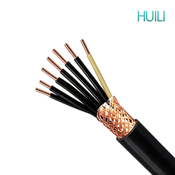
KVVP (PVC Shielded Control Cable): Added copper wire braided shielding, anti-electromagnetic interference, dedicated to frequency converters, sensors, and precision instruments;

KVV22 (Steel Tape Armored PVC Cable): Added steel tape armor, pressure resistant and rodent-proof, can be directly buried underground;

ZR-KVV (Flame Retardant PVC): Essential for fire protection, computer rooms, and high-rise buildings.

V. Applicable and Prohibited Scenarios

Applicable: Factory control cabinets, PLC low-voltage circuits, building fire alarm systems, underground cable trenches, indoor cable trays, mildly corrosive chemical workshops, and civil control projects with limited budgets.

Not Applicable: Near long-term high-temperature equipment, unprotected outdoor installation, halogen-free environmentally friendly locations such as subways/hospitals, extremely cold outdoor environments, and areas heavily soaked in oil.

STANDARD


IEC 60227
IEC 60502-1
IEC 60332
EN 50525
EN 50288
EN 50575
BS 5308
VDE 0281
CSA C22.2
AS/NZS 5000.3

No. of Cores and Nominal Cross Section Conductor Type Nominal Insulation Thickness  Nominal Sheath Thickness Approx.Overall Diameter Approx. Weight Max. D.C. Resistance of Conductor at 20℃ 
No. × mm² mm mm mm kg/km Ω/km
2×0.5 2 0.6 1.8 8.1 74 36
2×0.75 2 0.6 1.8 8.5 89 24.5
2×1 2 0.6 1.8 8.9 98 18.1
2×1.5 2 0.8 1.8 10.3 131 12.1
2×2.5 2 0.8 1.8 11.1 157 7.41
2×4 2 1 1.8 13 217 4.61
2×6 2 1 1.8 14.1 265 3.08
2×10 2 1 1.8 15.9 383 1.83
3×0.5 2 0.6 1.8 8.4 88 36
3×0.75 2 0.6 1.8 8.9 109 24.5
3×1 2 0.6 1.8 9.3 121 18.1
3×1.5 2 0.8 1.8 10.8 154 12.1
3×2.5 2 0.8 1.8 11.7 192 7.41
3×4 2 1 1.8 13.7 272 4.61
3×6 2 1 1.8 14.9 348 3.08
3×10 2 1 1.8 16.8 505 1.83
4×0.5 2 0.6 1.8 9 97 36
4×0.75 2 0.6 1.8 9.5 113 24.5
4×1 2 0.6 1.8 9.9 138 18.1
4×1.5 2 0.8 1.8 11.6 191 12.1
4×2.5 2 0.8 1.8 12.6 240 7.41
4×4 2 1 1.8 14.9 344 4.61
4×6 2 1 1.8 16.2 445 3.08
4×10 2 1 1.8 18.4 664 1.83
5×0.5 2 0.6 1.8 9.6 110 36
5×0.75 2 0.6 1.8 10.1 143 24.5
5×1 2 0.6 1.8 10.6 161 18.1
5×1.5 2 0.8 1.8 12.5 220 12.1
5×2.5 2 0.8 1.8 13.6 285 7.41
5×4 2 1 1.8 16.2 412 4.61
5×6 2 1 1.8 17.6 523 3.08
5×10 2 1 1.8 20.1 799 1.83
No. of Cores and Nominal Cross Section Conductor Type Nominal Insulation Thickness  Nominal Sheath Thickness Approx.Overall Diameter Approx. Weight Max. D.C. Resistance of Conductor at 20℃ 
6×0.75 2 0.6 1.8 10.8 147 24.5
6×1 2 0.6 1.8 11.4 170 18.1
6×1.5 2 0.8 1.8 13.5 239 12.1
6×2.5 2 0.8 1.8 14.7 311 7.41
6×4 2 1 1.8 17.6 455 4.61
6×6 2 1 1.8 19.2 596 3.08
6×10 2 1 1.8 21.9 868 1.83
7×0.5 2 0.6 1.8 10.2 131 36
7×0.75 2 0.6 1.8 10.8 157 24.5
7×1 2 0.6 1.8 11.4 182 18.1
7×1.5 2 0.8 1.8 13.5 259 12.1
7×2.5 2 0.8 1.8 14.7 341 7.41
7×4 2 1 1.8 17.6 504 4.61
7×6 2 1 1.8 19.2 657 3.08
7×10 2 1 1.8 21.9 962 1.83
8×0.5 2 0.6 1.8 11.1 150 36
8×0.75 2 0.6 1.8 11.9 180 24.5
8×1 2 0.6 1.8 12.5 209 18.1
8×1.5 2 0.8 1.8 14.9 298 12.1
8×2.5 2 0.8 1.8 16.4 392 7.41
8×4 2 1 1.8 19.6 582 4.61
8×6 2 1 1.8 21.5 755 3.08
8×10 2 1 1.8 24.6 1111 1.83
9×0.5 2 0.6 1.8 11.9 167 36
9×0.75 2 0.6 1.8 12.7 203 24.5
9×1 2 0.6 1.8 13.4 235 18.1
9×1.5 2 0.8 1.8 16 334 12.1
9×2.5 2 0.8 1.8 17.6 442 7.41
9×4 2 1 1.8 21.2 655 4.61
9×6 2 1 1.8 23.2 857 3.08
9×10 2 1 1.8 26.7 1261 1.83
No. of Cores and Nominal Cross Section Conductor Type Nominal Insulation Thickness  Nominal Sheath Thickness Approx.Overall Diameter Approx. Weight Max. D.C. Resistance of Conductor at 20℃ 
10×0.75 2 0.6 1.8 13.1 216 24.5
10×1 2 0.6 1.8 13.9 252 18.1
10×1.5 2 0.8 1.8 16.7 360 12.1
10×2.5 2 0.8 1.8 18.3 478 7.41
10×4 2 1 1.8 22.1 711 4.61
10×6 2 1 1.8 24.3 932 3.08
10×10 2 1 1.8 27.9 1369 1.83
12×0.5 2 0.6 1.8 12.6 195 36
12×0.75 2 0.6 1.8 13.5 238 24.5
12×1 2 0.6 1.8 14.3 280 18.1
12×1.5 2 0.8 1.8 17.2 406 12.1
12×2.5 2 0.8 1.8 18.9 543 7.41
12×4 2 1 1.8 22.8 816 4.61
12×6 2 1 1.8 25.1 1072 3.08
14×0.5 2 0.6 1.8 13.2 217 36
14×0.75 2 0.6 1.8 14.1 266 24.5
14×1 2 0.6 1.8 14.9 314 18.1
14×1.5 2 0.8 1.8 18 459 12.1
14×2.5 2 0.8 1.8 19.8 617 7.41
14×4 2 1 1.8 24 932 4.61
14×6 2 1 1.8 26.3 1230 3.08
16×0.5 2 0.6 1.8 13.8 242 36
16×0.75 2 0.6 1.8 14.8 298 24.5
16×1 2 0.6 1.8 15.6 352 18.1
16×1.5 2 0.8 1.8 18.9 516 12.1
16×2.5 2 0.8 1.8 20.9 696 7.41
16×4 2 1 1.8 25.3 1055 4.61
16×6 2 1 1.8 27.8 1393 3.08
19×0.5 2 0.6 1.8 14.4 271 36
19×0.75 2 0.6 1.8 15.5 336 24.5
19×1 2 0.6 1.8 16.4 400 18.1
19×1.5 2 0.8 1.8 19.9 592 12.1
19×2.5 2 0.8 1.8 22 802 7.41
19×4 2 1 1.8 26.7 1222 4.61
19×6 2 1 1.9 29.9 1643 3.08
20×0.5 2 0.6 1.8 15.1 286 36
20×1 2 0.6 1.8 17.2 422 18.1
20×1.5 2 0.8 1.8 20.9 624 12.1
20×2.5 2 0.8 1.8 23.1 845 7.41
20×4 2 1 1.8 28.2 1288 4.61
20×6 2 1 1.9 31.5 1731 3.08
No. of Cores and Nominal Cross Section Conductor Type Nominal Insulation Thickness  Nominal Sheath Thickness Approx.Overall Diameter Approx. Weight Max. D.C. Resistance of Conductor at 20℃ 
21×0.75 2 0.6 1.8 16.2 366 24.5
21×1 2 0.6 1.8 17.2 436 18.1
21×1.5 2 0.8 1.8 20.9 647 12.1
21×2.5 2 0.8 1.8 23.1 879 7.41
21×4 2 1 1.8 28.2 1342 4.61
21×6 2 1 1.9 31.5 1804 3.08
22×0.5 2 0.6 1.8 15.8 309 36
22×0.75 2 0.6 1.8 17 385 24.5
22×1 2 0.6 1.8 18 458 18.1
22×1.5 2 0.8 1.8 22 679 12.1
22×2.5 2 0.8 1.8 24.4 922 7.41
22×4 2 1 1.9 30.2 1430 4.61
22×6 2 1 2 33.5 1908 3.08
24×0.5 2 0.6 1.8 16.5 338 36
24×0.75 2 0.6 1.8 17.8 420 24.5
24×1 2 0.6 1.8 18.8 500 18.1
24×1.5 2 0.8 1.8 23 739 12.1
24×2.5 2 0.8 1.8 25.6 1006 7.41
24×4 2 1 1.9 31.7 1559 4.61
24×6 2 1 2 35.1 2084 3.08
27×0.5 2 0.6 1.8 16.8 362 36
27×0.75 2 0.6 1.8 18.1 453 24.5
27×1 2 0.6 1.8 19.2 542 18.1
27×1.5 2 0.8 1.8 23.5 808 12.1
27×2.5 2 0.8 1.8 26.1 1104 7.41
27×4 2 1 2 32.6 1732 4.61
27×6 2 1 2.1 36.1 2314 3.08
No. of Cores and Nominal Cross Section Conductor Type Nominal Insulation Thickness  Nominal Sheath Thickness Approx.Overall Diameter Approx. Weight Max. D.C. Resistance of Conductor at 20℃ 
30×0.75 2 0.6 1.8 18.7 493 24.5
30×1 2 0.6 1.8 19.9 592 18.1
30×1.5 2 0.8 1.8 24.3 885 12.1
30×2.5 2 0.8 1.8 27 1212 7.41
30×4 2 1 2 33.8 1903 4.61
30×6 2 1 2.1 37.4 2547 3.08
33×0.5 2 0.6 1.8 18 426 36
33×0.75 2 0.6 1.8 19.4 537 24.5
33×1 2 0.6 1.8 20.6 644 18.1
33×1.5 2 0.8 1.8 25.3 965 12.1
33×2.5 2 0.8 1.8 28.1 1325 7.41
33×4 2 1 2 35.1 2081 4.61
33×6 2 1 2.2 39.1 2804 3.08
37×0.5 2 0.6 1.8 18.6 464 36
37×0.75 2 0.6 1.8 20.1 587 24.5
37×1 2 0.6 1.8 21.3 707 18.1
37×1.5 2 0.8 1.8 26.2 1064 12.1
37×2.5 2 0.8 1.9 29.7 1485 7.41
37×4 2 1 2.1 36.7 2320 4.61
37×6 2 1 2.2 40.6 3108 3.08
44×0.5 2 0.6 1.8 20.7 549 36
44×0.75 2 0.6 1.8 22.4 694 24.5
44×1 2 0.6 1.8 23.8 836 18.1
44×1.5 2 0.8 1.9 29.9 1280 12.1
44×2.5 2 0.8 2 33.5 1774 7.41
44×4 2 1 2.2 41.4 2766 4.61
44×6 2 1 2.4 46.1 3728 3.08
48×0.5 2 0.6 1.8 21 581 36
48×0.75 2 0.6 1.8 22.7 739 24.5
48×1 2 0.6 1.8 24.2 893 18.1
48×1.5 2 0.8 1.9 30.4 1372 12.1
48×2.5 2 0.8 2 34 1906 7.41
48×4 2 1 2.3 42.3 2998 4.61
48×6 2 1 2.4 46.9 4017 3.08
52×0.5 2 0.6 1.8 21.6 621 36
52×0.75 2 0.6 1.8 23.3 791 24.5
52×1 2 0.6 1.8 24.8 957 18.1
52×1.5 2 0.8 1.9 31.2 1473 12.1
52×2.5 2 0.8 2 35 2048 7.41
52×4 2 1 2.3 43.5 3225 4.61
52×6 2 1 2.4 48.2 4326 3.08
52×6 2 1 2.4 48.2 4326 3.08
61×0.5 2 0.6 1.8 22.8 711 36
61×0.75 2 0.6 1.8 24.7 909 24.5
61×1 2 0.6 1.8 26.3 1102 18.1
61×1.5 2 0.8 2 33.3 1714 12.1
61×2.5 2 0.8 2.1 37.3 2386 7.41
61×4 2 1 2.4 46.4 3756 4.61
61×6 2 1 2.6 51.6 5065 3.08

get in touch

Huili Cable Co., Ltd. (formerly Luohe Huili Cable Co., Ltd. and Luohe Cable Factory) was founded in 1989 and was renamed Huili Cable Co., Ltd. on September 14, 2024. The company's registered capital is RMB 200 million.

    Home WhatsApp Mail Inquiry