Home > Products > Control Cables

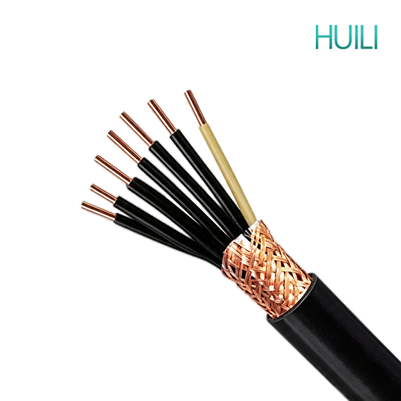
Control Cable N2XSY XLPE Insulated Copper Tape Shield- CU/XLPE/CTS/PVC- Cable

Control Cable N2XSY XLPE Insulated Copper Tape Shield- CU/XLPE/CTS/PVC- Cable

Control cables transmit control and measuring signals rather than heavy power. They are widely used in power stations, substations, industrial automation, fire protection, buildings, new energy and municipal projects. Various types with shielding, fire resistance, flexibility and armor are available to fit indoor, outdoor, buried and harsh industrial installation environments.

APPLICATION


Control cables transmit control and measuring signals rather than heavy power. They are widely used in power stations, substations, industrial automation, fire protection, buildings, new energy and municipal projects. Various types with shielding, fire resistance, flexibility and armor are available to fit indoor, outdoor, buried and harsh industrial installation environments.

CONSTRUCTION


9a69e5228722c4aaa28b82506f4bc5e9


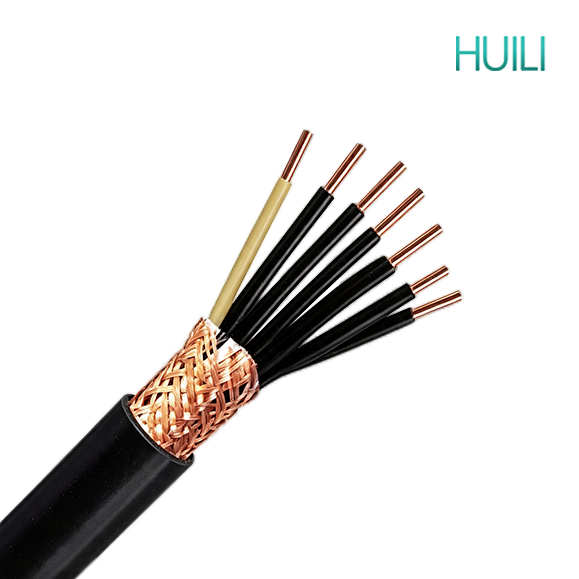
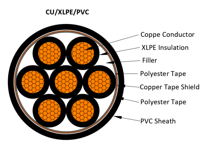
• Conductor: Copper, class 1, 2, solid, stranded round conductor
• Insulation: Cross-linked polyethylene XLPE
• Filler: Non-hygroscopic material
• Binder: Non-hygroscopic material
• Shield:Copper tape
• Outer sheath: Polyvinyl chloride PVC

• Rated Voltage:300/500V, 450/750V, 0.6/1kV


CHARACTERISTICS


Characteristics of XLPE Insulated Copper Tape Shielded Control Cables

1. Basic Structure & Standard Model

  • Model: KYJVP2, KYJVP2/22 (steel tape armored version)
  • Layer composition from inside out: tinned copper conductor → XLPE cross-linked polyethylene insulation → lapped copper tape shielding → PVC inner liner → PVC outer sheath (armored type adds double steel tape between liner and outer sheath)
  • Core positioning: control cable integrating high heat resistance, superior high-frequency anti-interference and wide environmental adaptability

2. Main Advantages

(1) Outstanding thermal performance inherited from XLPE insulation

  1. Long-term permissible operating temperature reaches 90°C, much higher than PVC insulated cables (70°C); short-circuit withstand temperature up to 250°C, larger ampacity under the same wire gauge.
  2. No softening or melting at high ambient temperatures, stable insulation performance for long-term laying in power distribution rooms, boiler auxiliary areas and densely arranged cable trenches.
  3. Excellent thermal aging resistance, effectively extending the service life under continuous high-temperature working conditions.

(2) Superior high-frequency anti-electromagnetic interference of copper tape shielding

  1. Continuous lapped copper tape achieves nearly 100% shielding coverage rate, without the gaps existing in copper wire braided shielding. It can completely isolate high-frequency interference generated by inverters, servo drives, high-power frequency conversion equipment.
  2. Forms a closed cylindrical conductive layer, eliminates shielding blind spots around the cable, effectively prevents signal distortion, data loss and misoperation of PLC, DCS and precision sensor control loops.
  3. Complete conductive loop for fast leakage current conduction to ground when insulation fails, improving secondary circuit safety protection response speed.
  4. Thinner copper tape occupies less radial space, resulting in smaller overall cable outer diameter and saving tray layout space; lower copper consumption than high-density braided shield, balancing shielding performance and cost.

(3) Excellent electrical insulation property of XLPE

Extremely low dielectric loss, stable insulation resistance that barely declines with temperature rise. Suitable for weak current precision signal transmission and industrial control loops with complex electromagnetic environment.

(4) Wide environmental adaptability

  1. UV-resistant XLPE material supports outdoor exposed laying (with complete outer sheath protection), no rapid pulverization or cracking under sunlight exposure, which PVC cables cannot achieve.
  2. Good low-temperature toughness, maintains flexibility at -40°C without embrittlement, applicable to cold northern outdoor fixed wiring without extra anti-freezing conduits.
  3. Strong resistance to moisture, dilute acid, alkali and mineral oil, stable operation in damp underground trenches, light-pollution chemical plants and water treatment workshops.

(5) Optional halogen-free low-smoke & flame-retardant grade

XLPE itself is halogen-free. WDZ-KYJVP2 low-smoke zero-halogen flame-retardant type releases only tiny amount of non-toxic, non-corrosive smoke during combustion, complying with fire protection standards of subways, hospitals, data centers and large commercial buildings. ZR-KYJVP2 flame-retardant version can slow flame spread for general fire-demand projects.

(6) Balanced mechanical performance

XLPE insulation avoids the high-temperature flow defect of PVC; it resists abrasion and slight impact during construction. The armored model KYJVP2/22 adds double steel tape, with excellent compression resistance and anti-rodent ability, supporting direct underground burial.

3. Disadvantages

(1) Fragile copper tape shielding layer

Thin lapped copper tape is prone to cracking or breaking under excessive stretching, sharp bending or violent dragging during construction. Once the shielding continuity is damaged, the high-frequency anti-interference capacity drops sharply. Copper wire braided shielded cables (KYJVP) have better tensile resistance for complex routing.

(2) Weak shielding effect against low-frequency magnetic field

Copper tape shielding is targeted at high-frequency radio interference; its ability to suppress low-frequency magnetic field interference from large transformers is inferior to copper wire braided shielding.

(3) Higher overall cost than PVC insulated copper tape shielded cables

Cross-linking production process increases manufacturing cost, and the finished cable price is 30%~50% higher than KVVP2 of the same specification, which raises investment for ordinary low-budget projects.

(4) Higher rigidity than PVC cables

XLPE insulation has higher hardness, requiring a larger minimum bending radius during installation; not suitable for wiring inside ultra-narrow compact cabinets with frequent sharp bends.

(5) Ordinary XLPE without flame retardant treatment is flammable

Non-flame-retardant KYJVP2 will continue burning when exposed to open fire; flame retardant or low-smoke halogen-free customization is mandatory for fire-critical public areas.

4. Classification of Common Types

  1. KYJVP2: Basic non-armored type, for indoor cable trays, control rooms and outdoor fixed laying with strong high-frequency interference sources.
  2. KYJVP2/22: Double steel tape armored copper tape shielded cable, pressure-proof, rodent-resistant, applicable for direct underground burial and heavy-load cable trenches.
  3. ZR-KYJVP2 / ZR-KYJVP2/22: Flame-retardant series, used for fire linkage control systems of high-rise buildings, factory fire control rooms.
  4. WDZ-KYJVP2 / WDZ-KYJVP2/22: Low-smoke halogen-free flame-retardant type, for subways, hospitals, data centers and other public buildings with strict environmental fire protection requirements.

5. Applicable & Inapplicable Scenarios

Suitable Scenarios

  • High-temperature power distribution rooms, boiler auxiliary control circuits
  • Outdoor exposed cable trays and cold northern industrial projects
  • Automation production lines with a large number of inverters and servo equipment
  • Precision instruments, DCS, PLC signal transmission loops requiring stable anti-high-frequency interference
  • Underground direct burial, damp light chemical workshops
  • Public buildings requiring halogen-free low-smoke fire safety performance

Unsuitable Scenarios

  • Wiring routes with frequent stretching, repeated sharp bending and violent dragging
  • Areas dominated by low-frequency magnetic interference near large transformers
  • Ultra-narrow cabinet wiring requiring ultra-soft flexible cables
  • Low-budget ordinary indoor control projects without high temperature and fire protection requirements

STANDARD


IEC 60227

IEC 60502-1

IEC 60332

EN 50525

EN 50288

EN 50575

BS 5308

VDE 0281

CSA C22.2

AS/NZS 5000.3

No. of Cores and Nominal Cross Section Conductor Type Nominal Insulation Thickness Nominal Copper Tape Thickness Nominal Sheath Thickness Approx. Overall Diameter Approx. Weight Max. D.C. Resistance of Conductor at 20℃
No. × mm² mm mm mm mm kg/km Ω/km
2×0.5 2 0.6 0.05 1.8 8.3 81 36
2×0.75 2 0.6 0.05 1.8 8.7 96 24.5
2×1 2 0.6 0.05 1.8 9 106 18.1
2×1.5 2 0.7 0.05 1.8 10 133 12.1
2×2.5 2 0.7 0.05 1.8 10.9 160 7.41
2×4 2 0.7 0.05 1.8 12 205 4.61
2×6 2 0.7 0.05 1.8 13 252 3.08
2×10 2 0.7 0.05 1.8 14.8 369 1.83
3×0.5 2 0.6 0.05 1.8 8.6 95 36
3×0.75 2 0.6 0.05 1.8 9 115 24.5
3×1 2 0.6 0.05 1.8 9.4 128 18.1
3×1.5 2 0.7 0.05 1.8 10.5 153 12.1
3×2.5 2 0.7 0.05 1.8 11.4 190 7.41
3×4 2 0.7 0.05 1.8 12.6 251 4.61
3×6 2 0.7 0.05 1.8 13.7 324 3.08
3×10 2 0.7 0.05 1.8 15.7 478 1.83
4×0.5 2 0.6 0.05 1.8 9.1 102 36
4×0.75 2 0.6 0.05 1.8 9.6 119 24.5
4×1 2 0.6 0.05 1.8 10.1 145 18.1
4×1.5 2 0.7 0.05 1.8 11.3 187 12.1
4×2.5 2 0.7 0.05 1.8 12.3 235 7.41
4×4 2 0.7 0.05 1.8 13.6 314 4.61
4×6 2 0.7 0.05 1.8 14.9 412 3.08
4×10 2 0.7 0.05 1.8 17.1 626 1.83
5×0.5 2 0.6 0.05 1.8 9.7 116 36
5×0.75 2 0.6 0.05 1.8 10.3 148 24.5
5×1 2 0.6 0.05 1.8 10.8 167 18.1
5×1.5 2 0.7 0.05 1.8 12.1 213 12.1
5×2.5 2 0.7 0.05 1.8 13.3 277 7.41
5×4 2 0.7 0.05 1.8 14.7 373 4.61
5×6 2 0.7 0.05 1.8 16.2 480 3.08
5×10 2 0.7 0.05 1.8 18.6 749 1.83
No. of Cores and Nominal Cross Section Conductor Type Nominal Insulation Thickness Nominal Copper Tape Thickness Nominal Sheath Thickness Approx. Overall Diameter Approx. Weight Max. D.C. Resistance of Conductor at 20℃
No. × mm² mm mm mm mm kg/km Ω/km
6×1 2 0.6 0.05 1.8 11.5 175 18.1
6×1.5 2 0.7 0.05 1.8 13 229 12.1
6×2.5 2 0.7 0.05 1.8 14.3 299 7.41
6×4 2 0.7 0.05 1.8 15.9 407 4.61
6×6 2 0.7 0.05 1.8 17.5 543 3.08
6×10 2 0.7 0.05 1.8 20.2 806 1.83
7×0.5 2 0.6 0.05 1.8 10.4 134 36
7×0.75 2 0.6 0.05 1.8 11 160 24.5
7×1 2 0.6 0.05 1.8 11.5 185 18.1
7×1.5 2 0.7 0.05 1.8 13 245 12.1
7×2.5 2 0.7 0.05 1.8 14.3 324 7.41
7×4 2 0.7 0.05 1.8 15.9 447 4.61
7×6 2 0.7 0.05 1.8 17.5 593 3.08
7×10 2 0.7 0.05 1.8 20.2 887 1.83
8×0.5 2 0.6 0.05 1.8 11.3 154 36
8×0.75 2 0.6 0.05 1.8 12 184 24.5
8×1 2 0.6 0.05 1.8 12.6 213 18.1
8×1.5 2 0.7 0.05 1.8 14.4 282 12.1
8×2.5 2 0.7 0.05 1.8 15.8 373 7.41
8×4 2 0.7 0.05 1.8 17.7 516 4.61
8×6 2 0.7 0.05 1.8 19.5 682 3.08
8×10 2 0.7 0.05 1.8 22.6 1025 1.83
9×0.5 2 0.6 0.05 1.8 12 171 36
9×0.75 2 0.6 0.05 1.8 12.8 207 24.5
9×1 2 0.6 0.05 1.8 13.5 239 18.1
9×1.5 2 0.7 0.05 1.8 15.4 316 12.1
9×2.5 2 0.7 0.05 1.8 17 420 7.41
9×4 2 0.7 0.05 1.8 19.1 580 4.61
9×6 2 0.7 0.05 1.8 21.1 774 3.08
9×10 2 0.7 0.05 1.8 24.5 1164 1.83
10×0.5 2 0.6 0.05 1.8 12.5 183 36
10×0.75 2 0.6 0.05 1.8 13.3 219 24.5
10×1 2 0.6 0.05 1.8 14 255 18.1
10×1.5 2 0.7 0.05 1.8 16 339 12.1
10×2.5 2 0.7 0.05 1.8 17.7 452 7.41
10×4 2 0.7 0.05 1.8 19.9 628 4.61
10×6 2 0.7 0.05 1.8 22 839 3.08
10×10 2 0.7 0.05 1.8 25.6 1260 1.83
No. of Cores and Nominal Cross Section Conductor Type Nominal Insulation Thickness Nominal Copper Tape Thickness Nominal Sheath Thickness Approx. Overall Diameter Approx. Weight Max. D.C. Resistance of Conductor at 20℃
No. × mm² mm mm mm mm kg/km Ω/km
12×1 2 0.6 0.05 1.8 14.4 279 18.1
12×1.5 2 0.7 0.05 1.8 16.5 377 12.1
12×2.5 2 0.7 0.05 1.8 18.2 509 7.41
12×4 2 0.7 0.05 1.8 20.5 713 4.61
12×6 2 0.7 0.05 1.8 22.7 958 3.08
14×0.5 2 0.6 0.05 1.8 13.3 216 36
14×0.75 2 0.6 0.05 1.8 14.2 265 24.5
14×1 2 0.6 0.05 1.8 15 312 18.1
14×1.5 2 0.7 0.05 1.8 17.2 423 12.1
14×2.5 2 0.7 0.05 1.8 19.1 575 7.41
14×4 2 0.7 0.05 1.8 21.5 811 4.61
14×6 2 0.7 0.05 1.8 23.9 1094 3.08
16×0.5 2 0.6 0.05 1.8 13.9 240 36
16×0.75 2 0.6 0.05 1.8 14.9 294 24.5
16×1 2 0.6 0.05 1.8 15.8 347 18.1
16×1.5 2 0.7 0.05 1.8 18.1 473 12.1
16×2.5 2 0.7 0.05 1.8 20.1 646 7.41
16×4 2 0.7 0.05 1.8 22.6 915 4.61
16×6 2 0.7 0.05 1.8 25.2 1236 3.08
19×0.5 2 0.6 0.05 1.8 14.6 266 36
19×0.75 2 0.6 0.05 1.8 15.6 329 24.5
19×1 2 0.6 0.05 1.8 16.5 391 18.1
19×1.5 2 0.7 0.05 1.8 19 537 12.1
19×2.5 2 0.7 0.05 1.8 21.1 739 7.41
19×4 2 0.7 0.05 1.8 23.8 1054 4.61
19×6 2 0.7 0.05 1.8 26.5 1432 3.08
20×0.5 2 0.6 0.05 1.8 15.2 280 36
20×0.75 2 0.6 0.05 1.8 16.4 347 24.5
20×1 2 0.6 0.05 1.8 17.3 413 18.1
20×1.5 2 0.7 0.05 1.8 20 567 12.1
20×2.5 2 0.7 0.05 1.8 22.2 779 7.41
20×4 2 0.7 0.05 1.8 25.1 1112 4.61
20×6 2 0.7 0.05 1.8 28 1510 3.08
21×0.5 2 0.6 0.05 1.8 15.2 287 36
21×0.75 2 0.6 0.05 1.8 16.4 357 24.5
21×1 2 0.6 0.05 1.8 17.3 426 18.1
21×1.5 2 0.7 0.05 1.8 20 586 12.1
21×2.5 2 0.7 0.05 1.8 22.2 808 7.41
21×4 2 0.7 0.05 1.8 25.1 1155 4.61
21×6 2 0.7 0.05 1.8 28 1572 3.08
No. of Cores and Nominal Cross Section Conductor Type Nominal Insulation Thickness Nominal Copper Tape Thickness Nominal Sheath Thickness Approx. Overall Diameter Approx. Weight Max. D.C. Resistance of Conductor at 20℃
No. × mm² mm mm mm mm kg/km Ω/km
22×1 2 0.6 0.05 1.8 18.2 447 18.1
22×1.5 2 0.7 0.05 1.8 21 616 12.1
22×2.5 2 0.7 0.05 1.8 23.4 849 7.41
22×4 2 0.7 0.05 1.8 26.4 1213 4.61
22×6 2 0.7 0.05 1.9 29.7 1663 3.08
24×0.5 2 0.6 0.05 1.8 16.7 329 36
24×0.75 2 0.6 0.05 1.8 17.9 409 24.5
24×1 2 0.6 0.05 1.8 19 486 18.1
24×1.5 2 0.7 0.05 1.8 22 669 12.1
24×2.5 2 0.7 0.05 1.8 24.5 925 7.41
24×4 2 0.7 0.05 1.8 27.8 1323 4.61
24×6 2 0.7 0.05 1.9 31.2 1817 3.08
27×0.5 2 0.6 0.05 1.8 17 349 36
27×0.75 2 0.6 0.05 1.8 18.3 438 24.5
27×1 2 0.6 0.05 1.8 19.4 524 18.1
27×1.5 2 0.7 0.05 1.8 22.4 727 12.1
27×2.5 2 0.7 0.05 1.8 25 1009 7.41
27×4 2 0.7 0.05 1.8 28.3 1452 4.61
27×6 2 0.7 0.05 1.9 31.9 1998 3.08
30×0.5 2 0.6 0.05 1.8 17.5 377 36
30×0.75 2 0.6 0.05 1.8 18.9 474 24.5
30×1 2 0.6 0.05 1.8 20 569 18.1
30×1.5 2 0.7 0.05 1.8 23.2 792 12.1
30×2.5 2 0.7 0.05 1.8 25.9 1105 7.41
30×4 2 0.7 0.05 1.9 29.6 1607 4.61
30×6 2 0.7 0.05 2 33.2 2212 3.08
33×0.5 2 0.6 0.05 1.8 18.1 408 36
33×0.75 2 0.6 0.05 1.8 19.5 514 24.5
33×1 2 0.6 0.05 1.8 20.7 618 18.1
33×1.5 2 0.7 0.05 1.8 24.1 862 12.1
33×2.5 2 0.7 0.05 1.8 26.9 1204 7.41
33×4 2 0.7 0.05 1.9 30.7 1756 4.61
33×6 2 0.7 0.05 2 34.5 2419 3.08
37×0.5 2 0.6 0.05 1.8 18.8 441 36
37×0.75 2 0.6 0.05 1.8 20.2 559 24.5
37×1 2 0.6 0.05 1.8 21.5 675 18.1
37×1.5 2 0.7 0.05 1.8 25 945 12.1
37×2.5 2 0.7 0.05 1.8 27.9 1326 7.41
37×4 2 0.7 0.05 2 32.1 1954 4.61
37×6 2 0.7 0.05 2.1 36.1 2694 3.08
No. of Cores and Nominal Cross Section Conductor Type Nominal Insulation Thickness Nominal Copper Tape Thickness Nominal Sheath Thickness Approx. Overall Diameter Approx. Weight Max. D.C. Resistance of Conductor at 20℃
No. × mm² mm mm mm mm kg/km Ω/km
44×1 2 0.6 0.05 1.8 24 796 18.1
44×1.5 2 0.7 0.05 1.8 28 1116 12.1
44×2.5 2 0.7 0.05 1.9 31.5 1583 7.41
44×4 2 0.7 0.05 2.1 36.3 2330 4.61
44×6 2 0.7 0.05 2.2 40.8 3214 3.08
48×0.5 2 0.6 0.05 1.8 21.2 547 36
48×0.75 2 0.6 0.05 1.8 22.9 698 24.5
48×1 2 0.6 0.05 1.8 24.3 846 18.1
48×1.5 2 0.7 0.05 1.8 28.4 1192 12.1
48×2.5 2 0.7 0.05 2 32.2 1711 7.41
48×4 2 0.7 0.05 2.1 36.8 2503 4.61
48×6 2 0.7 0.05 2.2 41.4 3458 3.08
52×0.5 2 0.6 0.05 1.8 21.7 582 36
52×0.75 2 0.6 0.05 1.8 23.5 744 24.5
52×1 2 0.6 0.05 1.8 25 905 18.1
52×1.5 2 0.7 0.05 1.9 29.4 1291 12.1
52×2.5 2 0.7 0.05 2 33.1 1836 7.41
52×4 2 0.7 0.05 2.1 37.9 2691 4.61
52×6 2 0.7 0.05 2.3 42.8 3741 3.08
61×0.5 2 0.6 0.05 1.8 23 661 36
61×0.75 2 0.6 0.05 1.8 24.8 850 24.5
61×1 2 0.6 0.05 1.8 26.5 1036 18.1
61×1.5 2 0.7 0.05 1.9 31.2 1483 12.1
61×2.5 2 0.7 0.05 2.1 35.3 2133 7.41
61×4 2 0.7 0.05 2.2 40.4 3131 4.61
61×6 2 0.7 0.05 2.4 45.7 4355 3.08

get in touch

Huili Cable Co., Ltd. (formerly Luohe Huili Cable Co., Ltd. and Luohe Cable Factory) was founded in 1989 and was renamed Huili Cable Co., Ltd. on September 14, 2024. The company's registered capital is RMB 200 million.

    Home WhatsApp Mail Inquiry