Home > Products > Control Cables

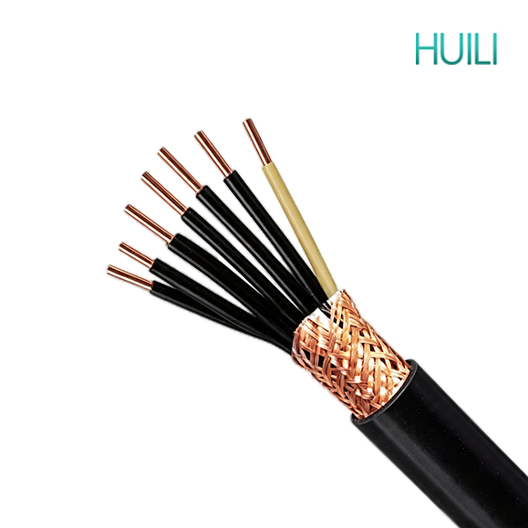
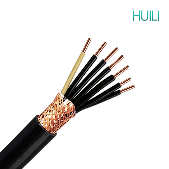
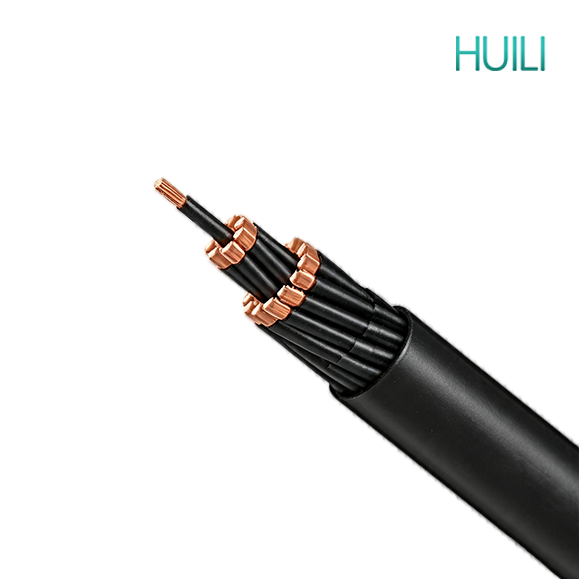
Control Cable NYSY Flame Retardant PVC Insulated -CU/PVC/CTS/PVC -Shield Cable

Control Cable NYSY Flame Retardant PVC Insulated -CU/PVC/CTS/PVC -Shield Cable

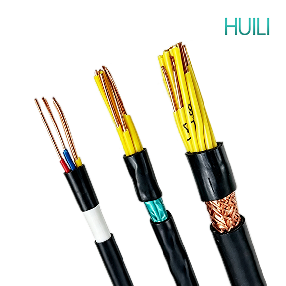
Control cables transmit control and measuring signals rather than heavy power. They are widely used in power stations, substations, industrial automation, fire protection, buildings, new energy and municipal projects. Various types with shielding, fire resistance, flexibility and armor are available to fit indoor, outdoor, buried and harsh industrial installation environments.

APPLICATION


Control cables transmit control and measuring signals rather than heavy power. They are widely used in power stations, substations, industrial automation, fire protection, buildings, new energy and municipal projects. Various types with shielding, fire resistance, flexibility and armor are available to fit indoor, outdoor, buried and harsh industrial installation environments.

Construction


5236cbf0aa92451db7b10b3b3eb84d59


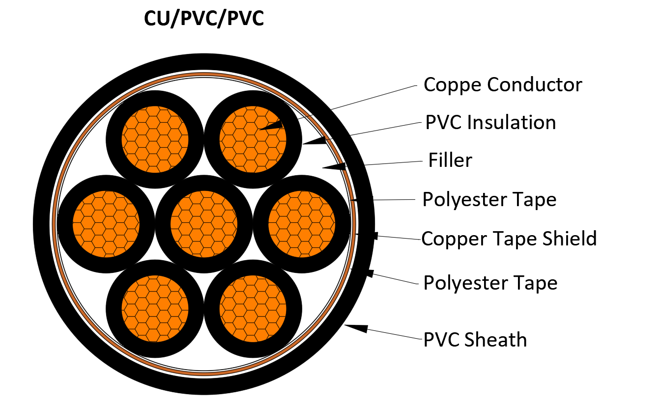
• Conductor: Conductor: Copper, class 1, 2, or 5, solid,stranded round or soft conductor
• Insulation: Polyvinyl chloride PVC
• Filler: Non-hygroscopic material
• Binder: Non-hygroscopic material
• Metal shield: copper tape
• Outer sheath: Polyvinyl chloride PVC

• Rated Voltage:300/500V, 450/750V, 0.6/1kV

CHARACTERISTICS

Characteristics of PVC Insulated Copper Tape Shielded Control Cables

1. Core Structure Composition

  • Conductor: Bare copper conductor
  • Insulation layer: PVC polyvinyl chloride insulation
  • Shield layer: Wrapped copper tape shielding (distinct from copper wire braided shielding)
  • Inner liner & outer sheath: PVC sheath
  • Main model: KVVP2, KVVP2/22 (steel tape armored type)

2. Advantages

(1) Excellent electromagnetic interference suppression performance

Copper tape forms a continuous closed shielding layer with 100% coverage rate, far higher than braided shield (80%-90% coverage). It effectively blocks high-frequency electromagnetic interference from inverters, high-power motors, power cabinets, and avoids signal distortion, data loss or control malfunction of PLC, sensors and instruments. It performs better against radio frequency and high-frequency interference.

(2) Uniform shielding effect around the cable circumference

Thin copper tape is tightly lapped wrapped, forming a complete conductive cylinder. No shielding blind spots exist on the cable surface, while braided shield has gaps between woven copper wires which weaken shielding effect locally.

(3) Stable grounding conduction & good fault leakage capacity

The continuous copper tape layer provides a complete grounding path. When insulation breakdown occurs, leakage current can be quickly conducted to the ground for rapid circuit protection triggering, improving circuit safety.

(4) Cost advantage vs dense braided shield cables

Compared with thick high-coverage copper wire braided control cables, copper tape shielding consumes less copper raw material, reducing overall cable cost while maintaining superior high-frequency shielding performance.

(5) Basic performance inherited from PVC insulation

  1. Flexible PVC insulation and sheath, easy bending and cabinet wiring;
  2. Resistant to dilute acid, alkali and light oil, suitable for general industrial damp cable trenches;
  3. Complete multi-core specifications from 2 cores to 61 cores for multi-loop centralized control;
  4. Optional flame retardant type (ZR-KVVP2) to slow flame spread in fire.

(6) Compact cable outer diameter

The thin lapped copper tape takes up less radial space than thick braided copper mesh, resulting in smaller overall cable diameter, saving tray laying space and lowering engineering layout difficulty.

3. Disadvantages

(1) Poor mechanical tensile resistance of the shielding layer

Copper tape is thin and prone to cracking or breaking under excessive stretching, sharp bending or violent dragging during construction. Once broken, the shielding continuity is destroyed and anti-interference ability drops sharply. Copper wire braided shield has better tensile resistance for complex laying routes.

(2) Weak low-frequency interference shielding capacity

Copper tape shielding excels at high-frequency interference, but its shielding effect on low-frequency magnetic field interference (such as nearby large transformers) is inferior to copper braided shielding.

(3) Inherent defects of PVC material

  1. Long-term allowable working temperature only 70℃, not applicable to high-temperature workshop environments;
  2. Poor UV resistance, cannot be laid exposed outdoors without pipe protection;
  3. Releases toxic hydrogen chloride corrosive smoke when burning, not allowed for halogen-free public buildings;
  4. Easy to harden and crack under long-term low temperature below -15℃.

(4) Limited anti-extrusion without armor

Non-armored KVVP2 cannot bear heavy external pressure or rodent bite; KVVP2/22 with steel tape armor must be selected for direct underground burial.

4. Common Model Classification & Additional Functions

  1. KVVP2: PVC insulated copper tape shielded control cable, for indoor fixed laying with high-frequency interference sources;
  2. KVVP2/22: Copper tape shield + double steel tape armor, pressure-resistant, anti-rodent, available for direct underground burial or heavy-load cable trenches;
  3. ZR-KVVP2 / ZR-KVVP2/22: Flame retardant grade, used for fire control rooms, high-rise building automatic control systems.

5. Suitable & Unsuitable Application Scenarios

Suitable Scenarios

  • Automation workshops with numerous inverters, servo motors and high-frequency equipment;
  • Precision instrument, sensor and DCS signal transmission circuits requiring stable signal;
  • Indoor cable trays, control rooms, covered cable trenches with strong high-frequency electromagnetic radiation;
  • Medium-budget engineering projects that demand superior high-frequency shielding without excessive cost.

Unsuitable Scenarios

  • Construction routes with frequent stretching, sharp repeated bending or heavy dragging;
  • Environments dominated by low-frequency magnetic field interference near large transformers;
  • Long-term high-temperature power distribution rooms, unprotected open-air outdoor laying;
  • Hospitals, subways, data centers and other places requiring halogen-free low-smoke cables;
  • Frigid northern open-air laying without anti-freezing conduit.

STANDARD


IEC 60227

IEC 60502-1

IEC 60332

EN 50525

EN 50288

EN 50575

BS 5308

VDE 0281

CSA C22.2

AS/NZS 5000.3

No. of Cores and Nominal Cross Section Conductor Type Nominal Insulation Thickness Nominal Copper Tape Thickness Nominal Sheath Thickness Approx. Overall Diameter Approx. Weight Max. D.C. Resistance of Conductor at 20℃
No. × mm² mm mm mm mm kg/km Ω/km
2×0.5 2 0.6 0.2 1.8 10.9 173 36
2×0.75 2 0.6 0.2 1.8 11.3 193 24.5
2×1 2 0.6 0.2 1.8 11.7 206 18.1
2×1.5 2 0.8 0.2 1.8 13.1 256 12.1
2×2.5 2 0.8 0.2 1.8 13.9 292 7.41
2×4 2 1 0.2 1.8 15.8 375 4.61
2×6 2 1 0.2 1.8 16.9 436 3.08
2×10 2 1 0.2 1.8 18.7 576 1.83
3×0.5 2 0.6 0.2 1.8 11.2 191 36
3×0.75 2 0.6 0.2 1.8 11.7 217 24.5
3×1 2 0.6 0.2 1.8 12.1 234 18.1
3×1.5 2 0.8 0.2 1.8 13.6 285 12.1
3×2.5 2 0.8 0.2 1.8 14.5 334 7.41
3×4 2 1 0.2 1.8 16.5 439 4.61
3×6 2 1 0.2 1.8 17.7 528 3.08
3×10 2 1 0.2 1.8 19.6 709 1.83
4×0.5 2 0.6 0.2 1.8 11.8 206 36
4×0.75 2 0.6 0.2 1.8 12.3 228 24.5
4×1 2 0.6 0.2 1.8 12.7 259 18.1
4×1.5 2 0.8 0.2 1.8 14.4 332 12.1
4×2.5 2 0.8 0.2 1.8 15.4 394 7.41
4×4 2 1 0.2 1.8 17.7 525 4.61
4×6 2 1 0.2 1.8 19 642 3.08
4×10 2 1 0.2 1.8 21.2 888 1.83
5×0.5 2 0.6 0.2 1.8 12.4 227 36
5×0.75 2 0.6 0.2 1.8 12.9 266 24.5
5×1 2 0.6 0.2 1.8 13.4 291 18.1
5×1.5 2 0.8 0.2 1.8 15.3 372 12.1
5×2.5 2 0.8 0.2 1.8 16.4 451 7.41
5×4 2 1 0.2 1.8 19 609 4.61
5×6 2 1 0.2 1.8 20.4 738 3.08
5×10 2 1 0.2 1.8 22.9 1042 1.83
No. of Cores and Nominal Cross Section Conductor Type Nominal Insulation Thickness Nominal Copper Tape Thickness Nominal Sheath Thickness Approx. Overall Diameter Approx. Weight Max. D.C. Resistance of Conductor at 20℃
No. × mm² mm mm mm mm kg/km Ω/km
6×0.75 2 0.6 0.2 1.8 13.6 279 24.5
6×1 2 0.6 0.2 1.8 14.2 308 18.1
6×1.5 2 0.8 0.2 1.8 16.3 403 12.1
6×2.5 2 0.8 0.2 1.8 17.5 489 7.41
6×4 2 1 0.2 1.8 20.4 668 4.61
6×6 2 1 0.2 1.8 22 829 3.08
6×10 2 1 0.2 1.8 24.7 1133 1.83
7×0.5 2 0.6 0.2 1.8 13 255 36
7×0.75 2 0.6 0.2 1.8 13.6 288 24.5
7×1 2 0.6 0.2 1.8 14.2 320 18.1
7×1.5 2 0.8 0.2 1.8 16.3 423 12.1
7×2.5 2 0.8 0.2 1.8 17.5 519 7.41
7×4 2 1 0.2 1.8 20.4 717 4.61
7×6 2 1 0.2 1.8 22 889 3.08
7×10 2 1 0.2 1.8 24.7 1227 1.83
8×0.5 2 0.6 0.2 1.8 13.9 285 36
8×0.75 2 0.6 0.2 1.8 14.7 324 24.5
8×1 2 0.6 0.2 1.8 15.3 361 18.1
8×1.5 2 0.8 0.2 1.8 17.7 479 12.1
8×2.5 2 0.8 0.2 1.8 19.2 590 7.41
8×4 2 1 0.2 1.8 22.4 819 4.61
8×6 2 1 0.2 1.8 24.3 1016 3.08
8×10 2 1 0.2 1.8 27.4 1409 1.83
9×0.5 2 0.6 0.2 1.8 14.7 312 36
9×0.75 2 0.6 0.2 1.8 15.5 357 24.5
9×1 2 0.6 0.2 1.8 16.2 398 18.1
9×1.5 2 0.8 0.2 1.8 18.8 529 12.1
9×2.5 2 0.8 0.2 1.8 20.4 656 7.41
9×4 2 1 0.2 1.8 24 912 4.61
9×6 2 1 0.2 1.8 26 1139 3.08
9×10 2 1 0.2 1.9 29.7 1597 1.83
10×0.5 2 0.6 0.2 1.8 15.1 329 36
10×0.75 2 0.6 0.2 1.8 15.9 376 24.5
10×1 2 0.6 0.2 1.8 16.7 420 18.1
10×1.5 2 0.8 0.2 1.8 19.5 563 12.1
10×2.5 2 0.8 0.2 1.8 21.1 700 7.41
10×4 2 1 0.2 1.8 24.9 979 4.61
10×6 2 1 0.2 1.8 27.1 1226 3.08
10×10 2 1 0.2 1.9 30.9 1721 1.83
No. of Cores and Nominal Cross Section Conductor Type Nominal Insulation Thickness Nominal Copper Tape Thickness Nominal Sheath Thickness Approx. Overall Diameter Approx. Weight Max. D.C. Resistance of Conductor at 20℃
No. × mm² mm mm mm mm kg/km Ω/km
12×0.75 2 0.6 0.2 1.8 16.3 402 24.5
12×1 2 0.6 0.2 1.8 17.1 453 18.1
12×1.5 2 0.8 0.2 1.8 20 615 12.1
12×2.5 2 0.8 0.2 1.8 21.7 772 7.41
12×4 2 1 0.2 1.8 25.6 1093 4.61
12×6 2 1 0.2 1.8 27.9 1376 3.08
14×0.5 2 0.6 0.2 1.8 16 377 36
14×0.75 2 0.6 0.2 1.8 16.9 437 24.5
14×1 2 0.6 0.2 1.8 17.7 495 18.1
14×1.5 2 0.8 0.2 1.8 20.8 677 12.1
14×2.5 2 0.8 0.2 1.8 22.6 857 7.41
14×4 2 1 0.2 1.8 26.8 1223 4.61
14×6 2 1 0.2 1.9 29.3 1562 3.08
16×0.5 2 0.6 0.2 1.8 16.6 409 36
16×0.75 2 0.6 0.2 1.8 17.6 477 24.5
16×1 2 0.6 0.2 1.8 18.4 542 18.1
16×1.5 2 0.8 0.2 1.8 21.7 745 12.1
16×2.5 2 0.8 0.2 1.8 23.7 949 7.41
16×4 2 1 0.2 1.8 28.1 1362 4.61
16×6 2 1 0.2 1.9 30.8 1744 3.08
19×0.5 2 0.6 0.2 1.8 17.2 446 36
19×0.75 2 0.6 0.2 1.8 18.3 524 24.5
19×1 2 0.6 0.2 1.8 19.2 599 18.1
19×1.5 2 0.8 0.2 1.8 22.7 832 12.1
19×2.5 2 0.8 0.2 1.8 24.8 1068 7.41
19×4 2 1 0.2 1.9 29.7 1559 4.61
19×6 2 1 0.2 2 32.9 2018 3.08
20×0.5 2 0.6 0.2 1.8 17.9 469 36
20×0.75 2 0.6 0.2 1.8 19 551 24.5
20×1 2 0.6 0.2 1.8 20 630 18.1
20×1.5 2 0.8 0.2 1.8 23.7 877 12.1
20×2.5 2 0.8 0.2 1.8 25.9 1126 7.41
20×4 2 1 0.2 1.9 31.2 1643 4.61
20×6 2 1 0.2 2 34.9 2165 3.08
21×0.5 2 0.6 0.2 1.8 17.9 478 36
21×0.75 2 0.6 0.2 1.8 19 563 24.5
21×1 2 0.6 0.2 1.8 20 645 18.1
21×1.5 2 0.8 0.2 1.8 23.7 900 12.1
21×2.5 2 0.8 0.2 1.8 25.9 1159 7.41
21×4 2 1 0.2 1.9 31.2 1697 4.61
21×6 2 1 0.2 2 34.9 2238 3.08
No. of Cores and Nominal Cross Section Conductor Type Nominal Insulation Thickness Nominal Copper Tape Thickness Nominal Sheath Thickness Approx. Overall Diameter Approx. Weight Max. D.C. Resistance of Conductor at 20℃
No. × mm² mm mm mm mm kg/km Ω/km
22×0.75 2 0.6 0.2 1.8 19.8 591 24.5
22×1 2 0.6 0.2 1.8 20.8 677 18.1
22×1.5 2 0.8 0.2 1.8 24.8 946 12.1
22×2.5 2 0.8 0.2 1.8 27.2 1218 7.41
22×4 2 1 0.2 2 33.6 1845 4.61
22×6 2 1 0.5 2.1 38.1 2723 3.08
24×0.5 2 0.6 0.2 1.8 19.3 538 36
24×0.75 2 0.6 0.2 1.8 20.6 635 24.5
24×1 2 0.6 0.2 1.8 21.6 728 18.1
24×1.5 2 0.8 0.2 1.8 25.8 1019 12.1
24×2.5 2 0.8 0.2 1.8 28.4 1316 7.41
24×4 2 1 0.2 2 35.1 1995 4.61
24×6 2 1 0.5 2.2 39.9 2957 3.08
27×0.5 2 0.6 0.2 1.8 19.6 566 36
27×0.75 2 0.6 0.2 1.8 20.9 673 24.5
27×1 2 0.6 0.2 1.8 22 775 18.1
27×1.5 2 0.8 0.2 1.8 26.3 1094 12.1
27×2.5 2 0.8 0.2 1.9 29.1 1433 7.41
27×4 2 1 0.2 2.1 36 2178 4.61
27×6 2 1 0.5 2.2 40.7 3190 3.08
30×0.5 2 0.6 0.2 1.8 20.2 603 36
30×0.75 2 0.6 0.2 1.8 21.5 720 24.5
30×1 2 0.6 0.2 1.8 22.7 832 18.1
30×1.5 2 0.8 0.2 1.8 27.1 1180 12.1
30×2.5 2 0.8 0.2 1.9 30 1553 7.41
30×4 2 1 0.5 2.1 38.4 2726 4.61
30×6 2 1 0.5 2.3 42.2 3473 3.08
33×0.5 2 0.6 0.2 1.8 20.8 645 36
33×0.75 2 0.6 0.2 1.8 22.2 772 24.5
33×1 2 0.6 0.2 1.8 23.4 894 18.1
33×1.5 2 0.8 0.2 1.8 28.1 1272 12.1
33×2.5 2 0.8 0.2 1.9 31.1 1679 7.41
33×4 2 1 0.5 2.2 39.9 2953 4.61
33×6 2 1 0.5 2.3 43.7 3749 3.08
37×0.5 2 0.6 0.2 1.8 21.4 690 36
37×0.75 2 0.6 0.2 1.8 22.9 831 24.5
37×1 2 0.6 0.2 1.8 24.1 966 18.1
37×1.5 2 0.8 0.2 1.9 29.2 1395 12.1
37×2.5 2 0.8 0.2 2 32.7 1858 7.41
37×4 2 1 0.5 2.2 41.3 3208 4.61
37×6 2 1 0.5 2.4 45.4 4110 3.08
No. of Cores and Nominal Cross Section Conductor Type Nominal Insulation Thickness Nominal Copper Tape Thickness Nominal Sheath Thickness Approx. Overall Diameter Approx. Weight Max. D.C. Resistance of Conductor at 20℃
No. × mm² mm mm mm mm kg/km Ω/km
44×0.75 2 0.6 0.2 1.8 25.2 965 24.5
44×1 2 0.6 0.2 1.8 26.6 1125 18.1
44×1.5 2 0.8 0.2 2 32.9 1656 12.1
44×2.5 2 0.8 0.5 2.1 38.1 2589 7.41
44×4 2 1 0.5 2.4 46.6 3831 4.61
44×6 2 1 0.5 2.5 51.1 4884 3.08
48×0.5 2 0.6 0.2 1.8 23.8 836 36
48×0.75 2 0.6 0.2 1.8 25.5 1015 24.5
48×1 2 0.6 0.2 1.8 27 1186 18.1
48×1.5 2 0.8 0.2 2 33.8 1791 12.1
48×2.5 2 0.8 0.5 2.2 38.8 2752 7.41
48×4 2 1 0.5 2.4 47.3 4061 4.61
48×6 2 1 0.5 2.6 52.1 5215 3.08
52×0.5 2 0.6 0.2 1.8 24.4 883 36
52×0.75 2 0.6 0.2 1.8 26.1 1074 24.5
52×1 2 0.6 0.2 1.8 27.6 1259 18.1
52×1.5 2 0.8 0.2 2 34.6 1903 12.1
52×2.5 2 0.8 0.5 2.2 39.8 2917 7.41
52×4 2 1 0.5 2.5 48.7 4338 4.61
52×6 2 1 0.5 2.6 53.4 5556 3.08
61×0.5 2 0.6 0.2 1.8 25.6 987 36
61×0.75 2 0.6 0.2 1.8 27.5 1208 24.5
61×1 2 0.6 0.2 1.9 29.3 1434 18.1
61×1.5 2 0.8 0.5 2.1 37.9 2526 12.1
61×2.5 2 0.8 0.5 2.3 42.1 3309 7.41
61×4 2 1 0.5 2.6 51.6 4940 4.61
61×6 2 1 0.5 2.7 56.6 6351 3.08

get in touch

Huili Cable Co., Ltd. (formerly Luohe Huili Cable Co., Ltd. and Luohe Cable Factory) was founded in 1989 and was renamed Huili Cable Co., Ltd. on September 14, 2024. The company's registered capital is RMB 200 million.

    Home WhatsApp Mail Inquiry