Home > Products > Armoured Cable

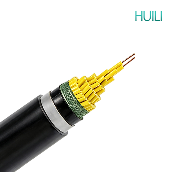
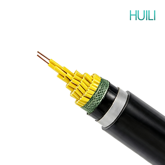
Control Cable N2XBY XLPE Insulated -CU/XLPE/PVC/STA/PVC- STA Steel Tape Armoured Cable

Control Cable N2XBY XLPE Insulated -CU/XLPE/PVC/STA/PVC- STA Steel Tape Armoured Cable

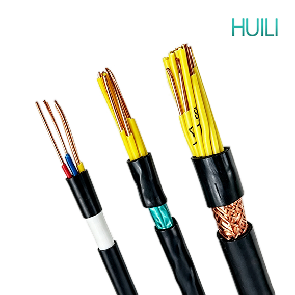
Control cables transmit control and measuring signals rather than heavy power. They are widely used in power stations, substations, industrial automation, fire protection, buildings, new energy and municipal projects. Various types with shielding, fire resistance, flexibility and armor are available to fit indoor, outdoor, buried and harsh industrial installation environments.

APPLICATION


Control cables transmit control and measuring signals rather than heavy power. They are widely used in power stations, substations, industrial automation, fire protection, buildings, new energy and municipal projects. Various types with shielding, fire resistance, flexibility and armor are available to fit indoor, outdoor, buried and harsh industrial installation environments.

CONSTRUCTION


827f19872a64e5b534bdbf447d831985


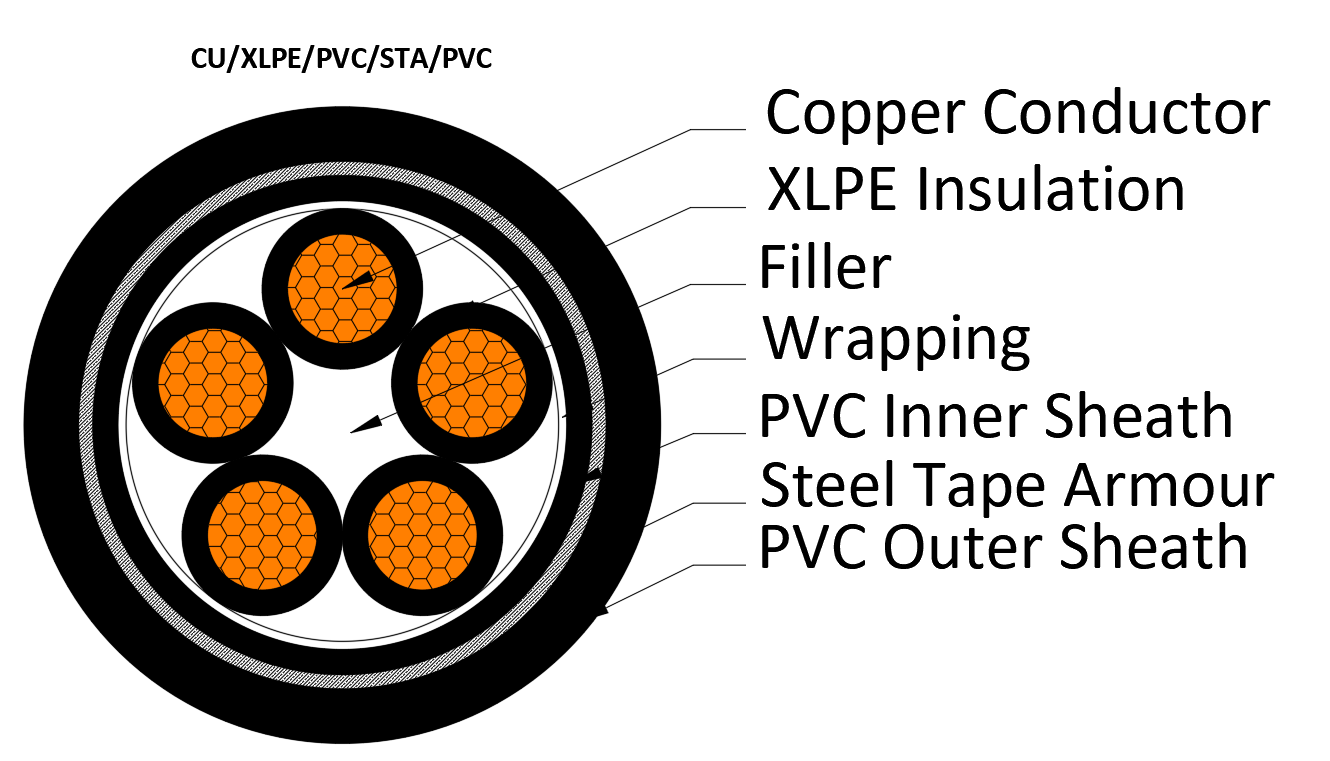
• Conductor: Copper, class 1, 2, solid, stranded round conductor
• Insulation: Cross-linked polyethylene XLPE
• Filler: Non-hygroscopic material
• Binder: Non-hygroscopic material
• Inner sheath: Polyvinyl chloride PVC
• Armour: Galvanized steel tape 
• Outer sheath: Polyvinyl chloride PVC

• Rated Voltage:300/500V, 450/750V, 0.6/1kV


CHARACTERISTICS


Characteristics of XLPE Insulated Steel Tape Armored Control Cables

1. Basic Structure & Standard Model

Main model: KYJV22

Layer structure from inside out: Copper conductor → XLPE cross-linked polyethylene insulation → PVC inner bedding → Double steel tape armor → PVC outer sheath

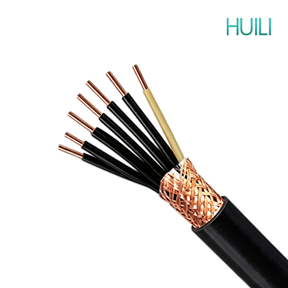
Shielded derivative models: KYJVP22 (copper braided shield), KYJVP2-22 (copper tape shield)

It combines XLPE’s excellent electrical & thermal performance with steel tape armor’s outstanding horizontal compression and anti-rodent capacity, designed mainly for horizontal direct burial, underground cable trenches and pipe galleries.

2. Core Advantages

(1) Superior thermal & electrical performance of XLPE insulation

  1. Long-term allowable operating temperature reaches 90°C, short-circuit withstand temperature up to 250°C. It has higher ampacity than PVC insulated cables with identical cross-section, suitable for densely arranged high-temperature cable trenches and power distribution rooms.
  2. Ultra-low dielectric loss and stable insulation resistance. Electrical performance barely deteriorates with temperature rise, ensuring reliable signal transmission for PLC, DCS, sensors and frequency conversion control loops.
  3. Inherent halogen-free property; WDZ-KYJV22 low-smoke zero-halogen version emits non-toxic, non-corrosive thin smoke during combustion, meeting strict fire protection standards for subways, hospitals and data centers. ZR-KYJV22 flame-retardant grade is available for general fire-demand projects.

(2) Outstanding horizontal mechanical protection from double steel tape armor

This is the core advantage distinguishing it from steel wire armored KYJV32:
  1. Two overlapping galvanized steel tapes form a full surrounding protective layer, delivering powerful resistance against horizontal extrusion, heavy rolling, rock squeezing and external impact. Ideal for direct burial under roads, factory yards and underground pipe galleries.
  2. Excellent anti-rodent and anti-termite performance; steel tape can prevent rodents from biting through the cable insulation.
  3. Good anti-corrosion: Galvanized steel tape resists mild soil corrosion, and the outer PVC sheath provides secondary isolation from damp, slightly acidic/alkaline soil.

(3) Wide environmental adaptability

  1. Strong UV and weather resistance: XLPE insulation avoids rapid aging, pulverization and cracking under long-term sunlight exposure, supporting outdoor open cable tray laying.
  2. Great low-temperature toughness: Remains flexible at -40°C without embrittlement, applicable to cold northern outdoor and underground projects without extra anti-freezing conduits.
  3. Good moisture and mild chemical resistance: Stable operation in damp tunnels, water treatment plants and light-pollution chemical workshops.

(4) Balanced construction performance

  1. Smaller outer diameter and lighter unit weight than steel wire armored KYJV32, lowering load requirements for cable brackets and pipe galleries.
  2. Smaller minimum bending radius than steel wire armored cables, more convenient for turning laying in trenches.
  3. Lower production cost than KYJV32, cost-effective for mass underground horizontal laying projects.

(5) Expandable anti-interference function

Equipped with copper braided shield (KYJVP22) or copper tape shield (KYJVP2-22) to suppress low-frequency magnetic interference and high-frequency radio interference respectively, solving signal distortion caused by inverters, high-power motors and transformers.

3. Disadvantages

(1) Poor vertical tensile capacity

Flat steel tape layers cannot bear large vertical pulling force. It is forbidden for long-distance vertical shaft or suspended overhead laying; KYJV32 steel wire armored cable must be selected for vertical tension scenarios.

(2) Weak anti-twist performance

Steel tape armor is prone to separation and deformation under long-term torsion, not suitable for inclined mine shaft winding laying.

(3) Rigid armor limits ultra-narrow bending

Compared with unarmored KYJV, KYJV22 requires a larger bending radius; it cannot be used for wiring inside compact small control cabinets.

(4) Ordinary XLPE is non-flame-retardant

Basic KYJV22 without flame retardant modification will sustain combustion under open fire; flame-retardant or low-smoke halogen-free customization is mandatory for public high-rise buildings and fire control systems.

4. Common Model Classification

  1. KYJV22: Basic unshielded steel tape armored control cable, for ordinary underground direct burial and horizontal cable trenches.
  2. KYJVP22: Copper wire braided shield + steel tape armor, good at suppressing low-frequency magnetic interference near transformers and heavy motors.
  3. KYJVP2-22: Copper tape shield + steel tape armor, excellent anti-high-frequency interference for automation production lines with many inverters.
  4. ZR-KYJV22 / ZR-KYJVP22: Flame-retardant series, used for fire linkage control circuits of high-rise buildings and underground pipe galleries.
  5. WDZ-KYJV22 / WDZ-KYJVP22: Low-smoke halogen-free flame-retardant type, for subways, hospitals, underground comprehensive pipe corridors and large commercial complexes.

5. Applicable & Inapplicable Scenarios

Suitable Scenarios

  1. Horizontal direct burial under roads, factory yards and green belts
  2. Underground cable trenches, municipal comprehensive pipe galleries, damp tunnels
  3. Outdoor open cable tray horizontal laying in high-temperature or cold industrial zones
  4. Projects requiring anti-rodent, anti-extrusion and anti-impact protection
  5. Industrial automation control loops with mild to medium electromagnetic interference (shielded versions)
  6. Light chemical plants and water treatment workshops with weak soil corrosion

Unsuitable Scenarios

  1. High-rise vertical cable shafts, mine vertical shafts and long-span suspended overhead laying (choose KYJV32 instead)
  2. Inclined winding tunnels with continuous torsion force
  3. Ultra-narrow control cabinets requiring small bending radius and flexible wiring
  4. Low-budget indoor cabinet wiring without underground mechanical protection demand
  5. Environments with strong acid, heavy oil and severe soil corrosion (special anti-corrosion sheath cables are required)

STANDARD


IEC 60227

IEC 60502-1

IEC 60332

EN 50525

EN 50288

EN 50575

BS 5308

VDE 0281

CSA C22.2

AS/NZS 5000.3

No. of Cores and Nominal Cross Section Conductor Type Nominal Insulation Thickness Nominal Steel Tape Thickness Nominal Sheath Thickness Approx. Overall Diameter Approx. Weight Max. D.C. Resistance of Conductor at 20℃
No. × mm² mm mm mm mm kg/km Ω/km
2×0.5 2 0.6 0.2 1.8 10.9 170 36
2×0.75 2 0.6 0.2 1.8 11.3 189 24.5
2×1 2 0.6 0.2 1.8 11.7 202 18.1
2×1.5 2 0.7 0.2 1.8 12.7 240 12.1
2×2.5 2 0.7 0.2 1.8 13.5 275 7.41
2×4 2 0.7 0.2 1.8 14.6 331 4.61
2×6 2 0.7 0.2 1.8 15.7 390 3.08
2×10 2 0.7 0.2 1.8 17.5 525 1.83
3×0.5 2 0.6 0.2 1.8 11.2 187 36
3×0.75 2 0.6 0.2 1.8 11.7 212 24.5
3×1 2 0.6 0.2 1.8 12.1 228 18.1
3×1.5 2 0.7 0.2 1.8 13.2 264 12.1
3×2.5 2 0.7 0.2 1.8 14.1 311 7.41
3×4 2 0.7 0.2 1.8 15.2 383 4.61
3×6 2 0.7 0.2 1.8 16.4 469 3.08
3×10 2 0.7 0.2 1.8 18.3 643 1.83
4×0.5 2 0.6 0.2 1.8 11.8 200 36
4×0.75 2 0.6 0.2 1.8 12.3 222 24.5
4×1 2 0.6 0.2 1.8 12.7 252 18.1
4×1.5 2 0.7 0.2 1.8 13.9 306 12.1
4×2.5 2 0.7 0.2 1.8 15 365 7.41
4×4 2 0.7 0.2 1.8 16.3 457 4.61
4×6 2 0.7 0.2 1.8 17.6 568 3.08
4×10 2 0.7 0.2 1.8 19.7 805 1.83
5×0.5 2 0.6 0.2 1.8 12.4 219 36
5×0.75 2 0.6 0.2 1.8 12.9 258 24.5
5×1 2 0.6 0.2 1.8 13.4 281 18.1
5×1.5 2 0.7 0.2 1.8 14.8 341 12.1
5×2.5 2 0.7 0.2 1.8 15.9 417 7.41
5×4 2 0.7 0.2 1.8 17.4 528 4.61
5×6 2 0.7 0.2 1.8 18.8 649 3.08
5×10 2 0.7 0.2 1.8 21.3 943 1.83
No. of Cores and Nominal Cross Section Conductor Type Nominal Insulation Thickness Nominal Steel Tape Thickness Nominal Sheath Thickness Approx. Overall Diameter Approx. Weight Max. D.C. Resistance of Conductor at 20℃
No. × mm² mm mm mm mm kg/km Ω/km
6×0.75 2 0.6 0.2 1.8 13.6 269 24.5
6×1 2 0.6 0.2 1.8 14.2 297 18.1
6×1.5 2 0.7 0.2 1.8 15.7 366 12.1
6×2.5 2 0.7 0.2 1.8 16.9 449 7.41
6×4 2 0.7 0.2 1.8 18.6 574 4.61
6×6 2 0.7 0.2 1.8 20.2 726 3.08
6×10 2 0.7 0.2 1.8 22.9 1016 1.83
7×0.5 2 0.6 0.2 1.8 13 245 36
7×0.75 2 0.6 0.2 1.8 13.6 277 24.5
7×1 2 0.6 0.2 1.8 14.2 307 18.1
7×1.5 2 0.7 0.2 1.8 15.7 382 12.1
7×2.5 2 0.7 0.2 1.8 16.9 474 7.41
7×4 2 0.7 0.2 1.8 18.6 613 4.61
7×6 2 0.7 0.2 1.8 20.2 775 3.08
7×10 2 0.7 0.2 1.8 22.9 1097 1.83
8×0.5 2 0.6 0.2 1.8 13.9 274 36
8×0.75 2 0.6 0.2 1.8 14.7 311 24.5
8×1 2 0.6 0.2 1.8 15.3 346 18.1
8×1.5 2 0.7 0.2 1.8 17 432 12.1
8×2.5 2 0.7 0.2 1.8 18.5 539 7.41
8×4 2 0.7 0.2 1.8 20.3 700 4.61
8×6 2 0.7 0.2 1.8 22.2 885 3.08
8×10 2 0.7 0.2 1.8 25.3 1260 1.83
9×0.5 2 0.6 0.2 1.8 14.7 299 36
9×0.75 2 0.6 0.2 1.8 15.5 342 24.5
9×1 2 0.6 0.2 1.8 16.2 381 18.1
9×1.5 2 0.7 0.2 1.8 18.1 477 12.1
9×2.5 2 0.7 0.2 1.8 19.7 598 7.41
9×4 2 0.7 0.2 1.8 21.7 778 4.61
9×6 2 0.7 0.2 1.8 23.8 993 3.08
9×10 2 0.7 0.2 1.8 27.2 1418 1.83
10×0.5 2 0.6 0.2 1.8 15.1 314 36
10×0.75 2 0.6 0.2 1.8 15.9 359 24.5
10×1 2 0.6 0.2 1.8 16.7 402 18.1
10×1.5 2 0.7 0.2 1.8 18.7 506 12.1
10×2.5 2 0.7 0.2 1.8 20.3 637 7.41
10×4 2 0.7 0.2 1.8 22.5 834 4.61
10×6 2 0.7 0.2 1.8 24.7 1067 3.08
10×10 2 0.7 0.2 1.8 28.3 1525 1.83
No. of Cores and Nominal Cross Section Conductor Type Nominal Insulation Thickness Nominal Steel Tape Thickness Nominal Sheath Thickness Approx. Overall Diameter Approx. Weight Max. D.C. Resistance of Conductor at 20℃
No. × mm² mm mm mm mm kg/km Ω/km
12×0.75 2 0.6 0.2 1.8 16.3 382 24.5
12×1 2 0.6 0.2 1.8 17.1 431 18.1
12×1.5 2 0.7 0.2 1.8 19.1 549 12.1
12×2.5 2 0.7 0.2 1.8 20.9 699 7.41
12×4 2 0.7 0.2 1.8 23.1 926 4.61
12×6 2 0.7 0.2 1.8 25.4 1193 3.08
14×0.5 2 0.6 0.2 1.8 16 356 36
14×0.75 2 0.6 0.2 1.8 16.9 414 24.5
14×1 2 0.6 0.2 1.8 17.7 469 18.1
14×1.5 2 0.7 0.2 1.8 19.9 603 12.1
14×2.5 2 0.7 0.2 1.8 21.7 773 7.41
14×4 2 0.7 0.2 1.8 24.1 1034 4.61
14×6 2 0.7 0.2 1.8 26.5 1341 3.08
16×0.5 2 0.6 0.2 1.8 16.6 386 36
16×0.75 2 0.6 0.2 1.8 17.6 451 24.5
16×1 2 0.6 0.2 1.8 18.4 512 18.1
16×1.5 2 0.7 0.2 1.8 20.8 662 12.1
16×2.5 2 0.7 0.2 1.8 22.7 855 7.41
16×4 2 0.7 0.2 1.8 25.3 1150 4.61
16×6 2 0.7 0.2 1.8 27.8 1497 3.08
19×0.5 2 0.6 0.2 1.8 17.2 418 36
19×0.75 2 0.6 0.2 1.8 18.3 493 24.5
19×1 2 0.6 0.2 1.8 19.2 564 18.1
19×1.5 2 0.7 0.2 1.8 21.7 735 12.1
19×2.5 2 0.7 0.2 1.8 23.8 958 7.41
19×4 2 0.7 0.2 1.8 26.5 1301 4.61
19×6 2 0.7 0.2 1.9 29.4 1719 3.08
20×0.5 2 0.6 0.2 1.8 17.9 440 36
20×0.75 2 0.6 0.2 1.8 19 518 24.5
20×1 2 0.6 0.2 1.8 20 593 18.1
20×1.5 2 0.7 0.2 1.8 22.6 775 12.1
20×2.5 2 0.7 0.2 1.8 24.9 1010 7.41
20×4 2 0.7 0.2 1.8 27.8 1371 4.61
20×6 2 0.7 0.2 1.9 30.8 1813 3.08
21×0.5 2 0.6 0.2 1.8 17.9 447 36
21×0.75 2 0.6 0.2 1.8 19 528 24.5
21×1 2 0.6 0.2 1.8 20 606 18.1
21×1.5 2 0.7 0.2 1.8 22.6 794 12.1
21×2.5 2 0.7 0.2 1.8 24.9 1039 7.41
21×4 2 0.7 0.2 1.8 27.8 1415 4.61
21×6 2 0.7 0.2 1.9 30.8 1875 3.08
No. of Cores and Nominal Cross Section Conductor Type Nominal Insulation Thickness Nominal Steel Tape Thickness Nominal Sheath Thickness Approx. Overall Diameter Approx. Weight Max. D.C. Resistance of Conductor at 20℃
No. × mm² mm mm mm mm kg/km Ω/km
22×0.75 2 0.6 0.2 1.8 19.8 554 24.5
22×1 2 0.6 0.2 1.8 20.8 637 18.1
22×1.5 2 0.7 0.2 1.8 23.7 834 12.1
22×2.5 2 0.7 0.2 1.8 26 1091 7.41
22×4 2 0.7 0.2 1.9 29.3 1499 4.61
22×6 2 0.7 0.2 2 32.9 1996 3.08
24×0.5 2 0.6 0.2 1.8 19.3 503 36
24×0.75 2 0.6 0.2 1.8 20.6 595 24.5
24×1 2 0.6 0.2 1.8 21.6 684 18.1
24×1.5 2 0.7 0.2 1.8 24.6 898 12.1
24×2.5 2 0.7 0.2 1.8 27.2 1178 7.41
24×4 2 0.7 0.2 1.9 30.6 1623 4.61
24×6 2 0.7 0.2 2 34.7 2202 3.08
27×0.5 2 0.6 0.2 1.8 19.6 526 36
27×0.75 2 0.6 0.2 1.8 20.9 628 24.5
27×1 2 0.6 0.2 1.8 22 725 18.1
27×1.5 2 0.7 0.2 1.8 25.1 959 12.1
27×2.5 2 0.7 0.2 1.8 27.7 1268 7.41
27×4 2 0.7 0.2 1.9 31.2 1758 4.61
27×6 2 0.7 0.2 2 35.4 2392 3.08
30×0.5 2 0.6 0.2 1.8 20.2 560 36
30×0.75 2 0.6 0.2 1.8 21.5 670 24.5
30×1 2 0.6 0.2 1.8 22.7 777 18.1
30×1.5 2 0.7 0.2 1.8 25.9 1033 12.1
30×2.5 2 0.7 0.2 1.8 28.6 1372 7.41
30×4 2 0.7 0.2 2 32.7 1938 4.61
30×6 2 0.7 0.5 2.1 38 2977 3.08
33×0.5 2 0.6 0.2 1.8 20.8 597 36
33×0.75 2 0.6 0.2 1.8 22.2 717 24.5
33×1 2 0.6 0.2 1.8 23.4 833 18.1
33×1.5 2 0.7 0.2 1.8 26.7 1111 12.1
33×2.5 2 0.7 0.2 1.9 29.7 1496 7.41
33×4 2 0.7 0.2 2 34.3 2135 4.61
No. of Cores and Nominal Cross Section Conductor Type Nominal Insulation Thickness Nominal Steel Tape Thickness Nominal Sheath Thickness Approx. Overall Diameter Approx. Weight Max. D.C. Resistance of Conductor at 20℃
No. × mm² mm mm mm mm kg/km Ω/km
37×0.5 2 0.6 0.2 1.8 21.4 636 36
37×0.75 2 0.6 0.2 1.8 22.9 769 24.5
37×1 2 0.6 0.2 1.8 24.1 898 18.1
37×1.5 2 0.7 0.2 1.8 27.6 1204 12.1
37×2.5 2 0.7 0.2 1.9 30.8 1628 7.41
37×4 2 0.7 0.2 2.1 35.7 2349 4.61
37×6 2 0.7 0.5 2.2 40.8 3520 3.08
44×0.5 2 0.6 0.2 1.8 23.5 736 36
44×0.75 2 0.6 0.2 1.8 25.2 892 24.5
44×1 2 0.6 0.2 1.8 26.6 1044 18.1
44×1.5 2 0.7 0.2 1.9 30.8 1418 12.1
44×2.5 2 0.7 0.2 2 35.1 1973 7.41
44×4 2 0.7 0.5 2.2 41 3159 4.61
44×6 2 0.7 0.5 2.4 45.7 4162 3.08
48×0.5 2 0.6 0.2 1.8 23.8 766 36
48×0.75 2 0.6 0.2 1.8 25.5 935 24.5
48×1 2 0.6 0.2 1.8 27 1098 18.1
48×1.5 2 0.7 0.2 1.9 31.3 1500 12.1
48×2.5 2 0.7 0.2 2.1 35.8 2108 7.41
48×4 2 0.7 0.5 2.2 41.6 3346 4.61
48×6 2 0.7 0.5 2.4 46.8 4466 3.08
52×0.5 2 0.6 0.2 1.8 24.4 807 36
52×0.75 2 0.6 0.2 1.8 26.1 988 24.5
52×1 2 0.6 0.2 1.8 27.6 1163 18.1
52×1.5 2 0.7 0.2 2 32.5 1619 12.1
52×2.5 2 0.7 0.5 2.1 37.9 2598 7.41
52×4 2 0.7 0.5 2.3 42.8 3575 4.61
52×6 2 0.7 0.5 2.4 48 4756 3.08
61×0.5 2 0.6 0.2 1.8 25.6 898 36
61×0.5 2 0.6 0.2 1.8 25.6 898 36
61×0.75 2 0.6 0.2 1.8 27.5 1107 24.5
61×1 2 0.6 0.2 1.9 29.3 1323 18.1
61×1.5 2 0.7 0.2 2 34.7 1868 12.1
61×2.5 2 0.7 0.5 2.2 40.1 2942 7.41
61×4 2 0.7 0.5 2.4 45.4 4070 4.61
61×6 2 0.7 0.5 2.5 50.8 5434 3.08

get in touch

Huili Cable Co., Ltd. (formerly Luohe Huili Cable Co., Ltd. and Luohe Cable Factory) was founded in 1989 and was renamed Huili Cable Co., Ltd. on September 14, 2024. The company's registered capital is RMB 200 million.

    Home WhatsApp Mail Inquiry