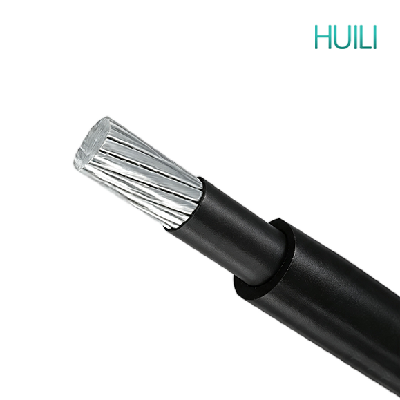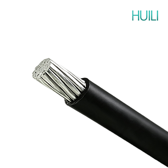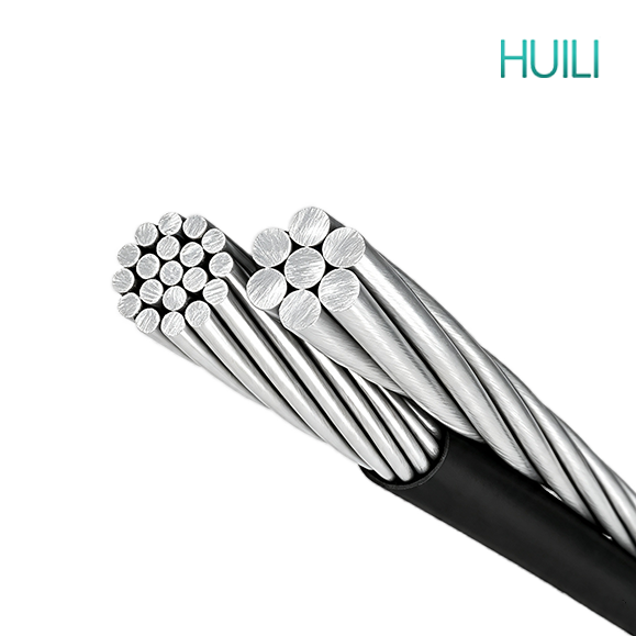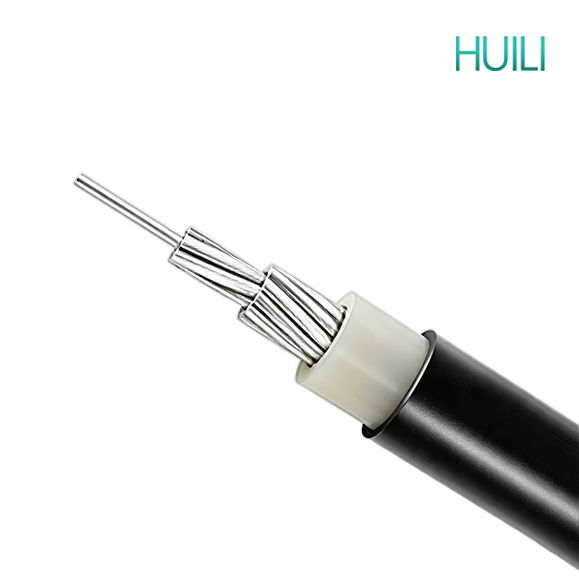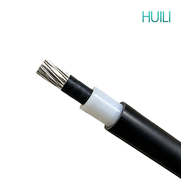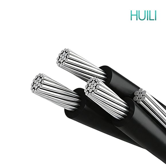
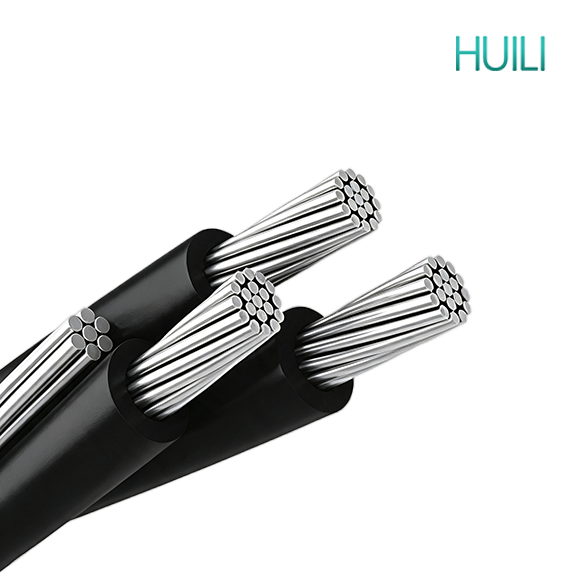
600/1000V ABC Aerial Bundled Cable(NFC 33-209)
Aerial Bundled Cable is also called insulated ABC Cable, it be used in overhead distribution line of rated voltages 0.6/1kV and below.
Home > Products > Aerial Bundled Cable
Aerial Bundled Cable is also called insulated ABC Cable, it be used in overhead distribution line of rated voltages 0.6/1kV and below.
Aerial Bundled Cable is also called insulated ABC Cable, it be used in overhead distribution line of rated voltages 0.6/1kV and below. Primarily used for overhead service applications such as street lighting, outdoor lighting, and temporary service for construction. The conductor long-term operating temperatures not to exceed 90°C for cross-linked polyethylene (XLPE) insulated conductors.
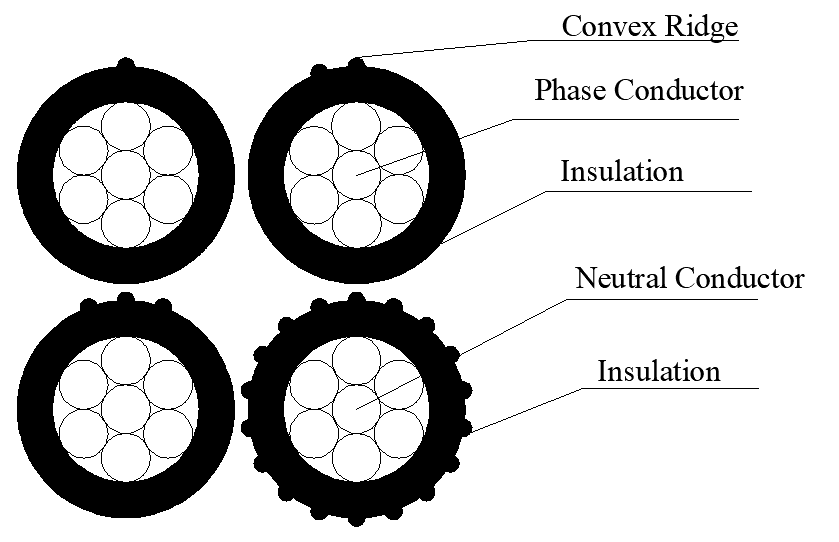
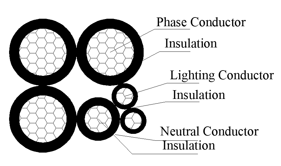
• Phase Conductor: Stranded,Circular compacted,Circular compressed AAC.
• Neutral Conductor: Stranded,Circular compacted or uncompacted AAAC.
• Street Lighting Conductor: Stranded,Circular compacted,Circular compressed AAC.
• Insulation: Cross-linked polyethylene (XLPE),Black color,Weather and UV resistant.
CHARACTERISTICS
It boasts excellent wind resistance and lightning protection capability. The cable has slight swing under strong wind conditions, which greatly decreases the probability of short-circuit faults resulting from line mutual collision. The outer insulation material is specially formulated with anti-UV additives. It can withstand long-term exposure to sunshine, rain erosion, frost and dew as well as atmospheric chemical corrosion, adapting to various outdoor harsh weather conditions. The installation process is relatively convenient. The messenger wire undertakes the overall tensile force, so fewer metal fittings and utility poles are needed during laying, simplifying construction work significantly. This type of cable occupies a smaller line passage space. It demands narrower safe clearance distance, making it highly applicable for power supply in communities, countryside and along both sides of roads.
Thanks to the integrated insulating sheath, the cable can stop accidental touching by pedestrians, tree branches and surrounding buildings, effectively eliminating hidden dangers of electric shock. It can prevent short circuit accidents triggered by tree branch friction or foreign objects bridging different conductors, stabilizing the operation of power distribution network. Compared with traditional bare overhead wires, aerial bundled cables pose far lower public safety risks and reduce incidents of power failures caused by external interference.
The comprehensive construction investment is lower than that of bare wire distribution systems equipped with cross arms and a large number of connecting accessories. Daily maintenance workload is minimal. Its service life ranges from 15 to 30 years subject to different insulation materials, cutting long-term operation and maintenance expenses. The cable effectively curbs unexpected power outages and reduces electric energy loss during power transmission, improving economic benefits of power supply.
It is widely used in low-voltage overhead power distribution projects in rural regions. It serves overhead power supply for residential blocks in urban areas. It can be applied to overhead wiring for road street lighting systems. It is an ideal choice for temporary electricity consumption on construction sites. It fits power supply layout in mountainous zones and areas with scattered electricity loads.
NFC 33-209
AS/NZS 3560.1
IEC 60502
BS 7870-5
HD 626 S1
AS/NZS 3599.1
| No. of Cores and Section Area | No. of Wires | Insulation Thickness | Approx. Diameter of Cable |
Max. DC. Resistance at 20℃ | Approx. Weight |
| mm2 | No. | mm | mm | Ω/km | kg/km |
| 2x16 | 7 | 1.2 | 14.3 | 1.91 | 133 |
| 2x25 | 7 | 1.4 | 17.5 | 1.20 | 202 |
| 2x35 | 7 | 1.6 | 20.3 | 0.868 | 275 |
| 2x50 | 7 | 1.6 | 22.5 | 0.641 | 352 |
| 2x70 | 12 | 1.8 | 26.7 | 0.443 | 497 |
| 2x95 | 19 | 1.8 | 30.3 | 0.320 | 658 |
| 2x120 | 19 | 1.8 | 32.7 | 0.253 | 801 |
| 4x16 | 7 | 1.2 | 17.3 | 1.91 | 264 |
| 4x25 | 7 | 1.4 | 21.1 | 1.20 | 401 |
| 4x35 | 7 | 1.6 | 24.5 | 0.868 | 549 |
| 4x50 | 7 | 1.6 | 27.1 | 0.641 | 701 |
| 4x70 | 12 | 1.8 | 32.3 | 0.443 | 992 |
| 4x95 | 19 | 1.8 | 36.7 | 0.320 | 1313 |
| 4x120 | 19 | 1.8 | 39.6 | 0.253 | 1599 |
| No. of Cores and Section Area | Phase Core | Neutral Core | Approx. Diameter of Cable |
Max. DC. Resistance at 20℃ | Approx. Weight | |||
| No. of Wires | Insulation Thickness | No. of Wires | Insulation Thickness | Phase | Neutral | |||
| mm2 | No. | mm | No. | mm | mm | Ω/km | Ω/km | kg/km |
| 1x25+1x54.6 | 7 | 1.4 | 7 | 1.6 | 21.5 | 1.20 | 0.63 | 311 |
| 1x35+1x54.6 | 7 | 1.6 | 7 | 1.6 | 22.9 | 0.868 | 0.63 | 347 |
| 1x50+1x54.6 | 7 | 1.6 | 7 | 1.6 | 24.0 | 0.641 | 0.63 | 386 |
| 1x70+1x54.6 | 12 | 1.8 | 7 | 1.6 | 26.1 | 0.443 | 0.63 | 458 |
| 1x95+1x54.6 | 19 | 1.8 | 7 | 1.6 | 27.9 | 0.320 | 0.63 | 539 |
| 1x70+1x70 | 12 | 1.8 | 7 | 1.5 | 26.9 | 0.443 | 0.50 | 493 |
| 1x95+1x70 | 19 | 1.8 | 7 | 1.5 | 28.7 | 0.320 | 0.50 | 573 |
| 1x120+1x70 | 19 | 1.8 | 7 | 1.5 | 29.9 | 0.253 | 0.50 | 645 |
| 1x120+1x95 | 19 | 1.8 | 19 | 1.6 | 32.1 | 0.253 | 0.343 | 739 |
| 1x150+1x95 | 19 | 1.7 | 19 | 1.6 | 33.8 | 0.206 | 0.343 | 821 |
| 3x25+1x54.6 | 7 | 1.4 | 7 | 1.6 | 23.7 | 1.20 | 0.63 | 510 |
| 3x35+1x54.6 | 7 | 1.6 | 7 | 1.6 | 26.3 | 0.868 | 0.63 | 621 |
| 3x50+1x54.6 | 7 | 1.6 | 7 | 1.6 | 28.3 | 0.641 | 0.63 | 735 |
| 3x70+1x54.6 | 12 | 1.8 | 7 | 1.6 | 32.1 | 0.443 | 0.63 | 953 |
| 3x95+1x54.6 | 19 | 1.8 | 7 | 1.6 | 35.4 | 0.320 | 0.63 | 1194 |
| 3x70+1x70 | 12 | 1.8 | 7 | 1.5 | 32.6 | 0.443 | 0.50 | 988 |
| 3x95+1x70 | 19 | 1.8 | 7 | 1.5 | 35.8 | 0.320 | 0.50 | 1229 |
| 3x120+1x70 | 19 | 1.8 | 7 | 1.5 | 38.0 | 0.253 | 0.50 | 1443 |
| 3x120+1x95 | 19 | 1.8 | 19 | 1.6 | 39.3 | 0.253 | 0.343 | 1538 |
| 3x150+1x95 | 19 | 1.7 | 19 | 1.6 | 42.4 | 0.206 | 0.343 | 1781 |
| No. of Cores and Section Area | Phase Core | Neutral Core | Street Lighting Core | Approx. Diameter of Cable |
Max. DC. Resistance at 20℃ | Approx. Weight | |||||
| No. of Wires | Insulation Thickness | No. of Wires | Insulation Thickness | No. of Wires | Insulation Thickness | Phase | Neutral | Street Lighting | |||
| mm2 | No. | mm | No. | mm | No. | mm | mm | Ω/km | Ω/km | Ω/km | kg/km |
| 3x25+1x54.6+1x16 | 7 | 1.4 | 7 | 1.6 | 7 | 1.2 | 30.2 | 1.20 | 0.63 | 1.91 | 572 |
| 3x35+1x54.6+1x16 | 7 | 1.6 | 7 | 1.6 | 7 | 1.2 | 33.0 | 0.868 | 0.63 | 1.91 | 683 |
| 3x50+1x54.6+1x16 | 7 | 1.6 | 7 | 1.6 | 7 | 1.2 | 35.2 | 0.641 | 0.63 | 1.91 | 798 |
| 3x70+1x54.6+1x16 | 12 | 1.8 | 7 | 1.6 | 7 | 1.2 | 39.4 | 0.443 | 0.63 | 1.91 | 1015 |
| 3x70+1x54.6+1x25 | 12 | 1.8 | 7 | 1.6 | 7 | 1.4 | 39.4 | 0.443 | 0.63 | 1.20 | 1050 |
| 3x70+1x70+1x16 | 12 | 1.8 | 7 | 1.5 | 7 | 1.2 | 40.2 | 0.443 | 0.50 | 1.91 | 1050 |
| 3x95+1x70+1x16 | 19 | 1.8 | 7 | 1.5 | 7 | 1.2 | 43.8 | 0.320 | 0.50 | 1.91 | 1291 |
| 3x120+1x70+1x16 | 19 | 1.8 | 7 | 1.5 | 7 | 1.2 | 46.2 | 0.253 | 0.50 | 1.91 | 1505 |
| 3x120+1x95+1x16 | 19 | 1.8 | 19 | 1.6 | 7 | 1.2 | 48.4 | 0.253 | 0.343 | 1.91 | 1599 |
| 3x150+1x95+1x16 | 19 | 1.7 | 19 | 1.6 | 7 | 1.2 | 51.8 | 0.206 | 0.343 | 1.91 | 1842 |
| 3x25+1x54.6+2x16 | 7 | 1.4 | 7 | 1.6 | 7 | 1.2 | 30.2 | 1.20 | 0.63 | 1.91 | 637 |
| 3x35+1x54.6+2x16 | 7 | 1.6 | 7 | 1.6 | 7 | 1.2 | 33.0 | 0.868 | 0.63 | 1.91 | 748 |
| 3x50+1x54.6+2x16 | 7 | 1.6 | 7 | 1.6 | 7 | 1.2 | 35.2 | 0.641 | 0.63 | 1.91 | 862 |
| 3x70+1x54.6+2x16 | 12 | 1.8 | 7 | 1.6 | 7 | 1.2 | 39.4 | 0.443 | 0.63 | 1.91 | 1080 |
| 3x70+1x54.6+2x25 | 12 | 1.8 | 7 | 1.6 | 7 | 1.4 | 39.4 | 0.443 | 0.63 | 1.20 | 1148 |
| 3x70+1x70+2x16 | 12 | 1.8 | 7 | 1.5 | 7 | 1.2 | 40.2 | 0.443 | 0.50 | 1.91 | 1116 |
| 3x95+1x70+2x16 | 19 | 1.8 | 7 | 1.5 | 7 | 1.2 | 43.8 | 0.320 | 0.50 | 1.91 | 1356 |
| 3x120+1x70+2x16 | 19 | 1.8 | 7 | 1.5 | 7 | 1.2 | 46.2 | 0.253 | 0.50 | 1.91 | 1575 |
| 3x120+1x95+2x16 | 19 | 1.8 | 19 | 1.6 | 7 | 1.2 | 48.4 | 0.253 | 0.343 | 1.91 | 1664 |
| 3x150+1x95+2x16 | 19 | 1.7 | 19 | 1.6 | 7 | 1.2 | 51.8 | 0.206 | 0.343 | 1.91 | 1917 |
| number of cores x nominal cross section | Nominal conductor diameter | Nominal insulation thickness | Nominal insulation screen thickness | Nominal sheath thickness | AAAC/1120 support conductor size | Nominal overall diameter | Weight | Continuous current rating, A | ||
| Still air | 1m/s wind | 2m/s wind | ||||||||
| mm^2 | mm | mm | mm | mm | No/mm | mm | kg/km | A | A | A |
| 6.35/11kV | ||||||||||
| 3x35 | 6.9 | 3.4 | 0.8 | 1.2 | 7/4.75 | 52.4 | 1370 | 110 | 155 | 185 |
| 3x50 | 8.1 | 3.4 | 0.8 | 1.2 | 7/4.75 | 54.6 | 1530 | 130 | 185 | 225 |
| 3x70 | 9.7 | 3.4 | 0.8 | 1.2 | 7/4.75 | 57.8 | 1790 | 160 | 235 | 280 |
| 3x95 | 11.4 | 3.4 | 0.8 | 1.2 | 7/4.75 | 61.3 | 2100 | 195 | 285 | 345 |
| 3x120 | 12.8 | 3.4 | 0.8 | 1.2 | 19/3.50 | 67.3 | 2540 | 230 | 335 | 405 |
| 3x150 | 14.2 | 3.4 | 0.8 | 1.2 | 19/3.50 | 70.1 | 2840 | 255 | 380 | 460 |
| 3x185 | 15.7 | 3.4 | 0.8 | 1.2 | 19/3.50 | 73.1 | 3190 | 295 | 440 | 530 |
| 12.7/22kV | ||||||||||
| 3x35 | 6.9 | 5.5 | 0.8 | 1.2 | 7/4.75 | 61 | 1780 | 110 | 155 | 180 |
| 3x50 | 8.1 | 5.5 | 0.8 | 1.2 | 7/4.75 | 63.3 | 1970 | 130 | 185 | 220 |
| 3x70 | 9.7 | 5.5 | 0.8 | 1.2 | 7/4.75 | 66.5 | 2260 | 160 | 230 | 275 |
| 3x95 | 11.4 | 5.5 | 0.8 | 1.2 | 7/4.75 | 69.9 | 2600 | 195 | 285 | 335 |
| 3x120 | 12.8 | 5.5 | 0.8 | 1.2 | 19/3.50 | 75.9 | 3070 | 225 | 330 | 395 |
| 3x150 | 14.2 | 5.5 | 0.8 | 1.2 | 19/3.50 | 78.7 | 3390 | 255 | 375 | 450 |
| 3x185 | 15.7 | 5.5 | 0.8 | 1.2 | 19/3.50 | 81.7 | 3760 | 290 | 435 | 520 |
| Number of cores x nominal cross section | min. breaking load of conductor strand | Current rating in the air | Outer diameter | Total weight |
| mm^2 | kN | A | mm | kg/km |
| 2x 16 RM | 1910 | 2,5 | 72 | 147 |
| 2x 25 RM | 1200 | 4,0 | 107 | 208 |
| 2x 35 RM | 0,868 | 5,5 | 132 | 277 |
| 2x 50 RM | 0,641 | 8,0 | 165 | 361 |
| 4x 16 RM | 1910 | 2,5 | 72 | 286 |
| 4x 25 RM | 1200 | 4,0 | 107 | 430 |
| 4x 35 RM | 0,868 | 5,5 | 132 | 553 |
| 4x 50 RM | 0,641 | 8,0 | 165 | 746 |
| 4x 70 RM | 0,443 | 10,7 | 205 | 1009 |
| 4x 95 RM | 0,320 | 13,7 | 240 | 1332 |
| 4x 120 RM | 0,253 | 18,6 | 290 | 1632 |
| 4x 35 + 1x 35 RM | 0,868 / 0,868 | 5,5 / 5,5 | 132 / 132 | 694 |
| 4x 50 + 1x 25 RM | 0,641 / 1,200 | 8,0 / 4,0 | 165 / 107 | 814 |
| 4x 50 + 1x 35 RM | 0,641 / 0,868 | 8,5 / 5,5 | 165 / 132 | 845 |
| 4x 70 + 1x 25 RM | 0,443 / 1,200 | 10,7 / 4,0 | 205 / 107 | 1105 |
| 4x 70 + 2x 25 RM | 0,443 / 1,200 | 10,7 / 4,0 | 205 / 107 | 1217 |
| 4x 70 + 1x 35 RM | 0,443 / 0,868 | 10,7 / 5,5 | 205 / 132 | 1150 |
| 4x 70 + 2x 35 RM | 0,443 / 0,868 | 10,7 / 5,5 | 205 / 132 | 1289 |
| 4x 95 + 1x 25 RM | 0,320 / 1,200 | 13,7 / 4,0 | 240 / 107 | 1438 |
| 4x 95 + 1x 35 RM | 0,320 / 0,868 | 13,7 / 5,5 | 240 / 132 | 1467 |
| 4x 95 + 2x 25 RM | 0,320 / 1,200 | 13,7 / 4,0 | 240 / 107 | 1544 |
Huili Cable Co., Ltd. (formerly Luohe Huili Cable Co., Ltd. and Luohe Cable Factory) was founded in 1989 and was renamed Huili Cable Co., Ltd. on September 14, 2024. The company's registered capital is RMB 200 million.