Home > Products > Armoured Cable

NYBY-CU/PVC/STA(ATA)/PVC Cable 0.6/1kV

NYBY-CU/PVC/STA(ATA)/PVC Cable 0.6/1kV

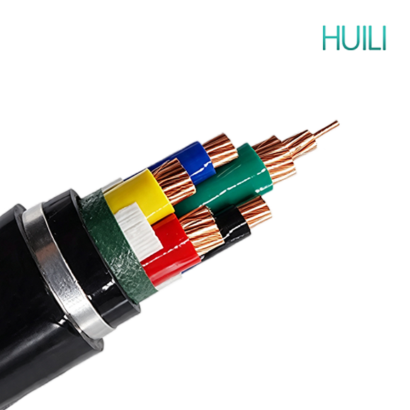
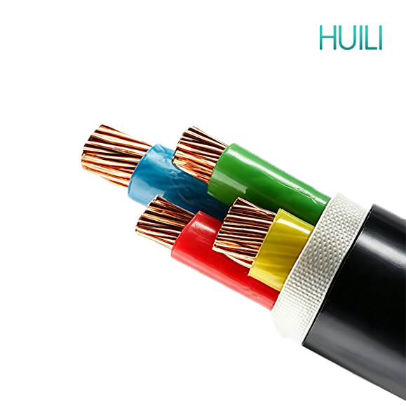
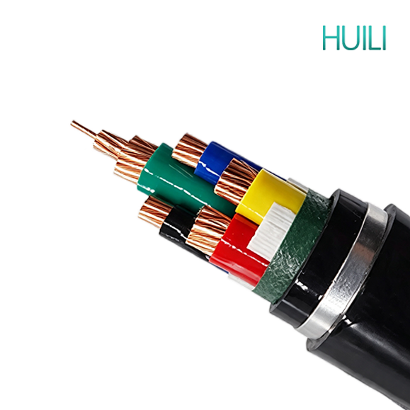
This low-voltage steel-tape armored(AL-tape) cable has a rated voltage of 0.6/1kV. Internally, it consists of copper/aluminum conductors and cross-linked polyethylene insulation, with double-layer galvanized steel tape armor and inner and outer PVC sheaths. The steel tape can withstand soil compression, impact from hard objects, and is resistant to rodent and termite damage, offering excellent compressive strength. This cable offers high cost-effectiveness and is a commonly used cable for outdoor buried power distribution.

APPLICATION

The cable is used for low voltage distribution power networks, electricity supply in low voltage installation systems, in buildings and operation stations main power supply. They are well adapted to underground use in industrial applications with an additional mechanical protection. And the cable can be laying indoor, tunnel and underground. Able to bear external mechanical force, but unable to bear large pulling force.

CONSTRUCTION

a8f9e30e985cf97239c9a5d5561fc05af6c5843e9e9134d75044d54d4ad806

● Conductor: Copper/Tinned copper, class 1 or class 2, solid or stranded, circular or circular compacted conductors
● Insulation: Polyvinyl chloride (PVC)/LSZH
● Filler: Non-hygroscopic material
● Binder: Non-hygroscopic material
● Inner sheath: Polyvinyl chloride (PVC)/LSZH/ZR-PVC
● Armour: Steel tape/Aluminum tape
● Outer sheath: Polyvinyl chloride (PVC)/LSZH/ZR-PVC

CHARACTERISTICS

I. Basic Structural Characteristics
Standard Structure (from inside to outside): Conductor → Insulation Layer → Inner Liner Layer → Double-Layer Galvanized Steel Strip Armor → PVC/LSZH Outer Sheath

1. Voltage Rating: Low-voltage general purpose 0.6/1kV; Armoring Process: Double-layer galvanized steel strip spiral wrapping, steel strip overlap rate ≥15%, forming a ring-shaped rigid protective layer.

2. Conductors are divided into copper core/aluminum core; Insulation is divided into two main categories: XLPE cross-linked (long-term 90℃) and PVC (long-term 70℃).

II. Core Characteristics of Mechanical Protection (Greatest Advantage)

1. Extremely strong radial compressive strength: Can withstand soil static pressure, vehicle rolling, stone compression, and earthwork excavation impact, suitable for direct underground burial; the ring-shaped steel strip structure disperses local heavy pressure, making it less prone to flattening the insulation.

2. Rodent and insect resistance, shear resistance: The metal steel strip forms a physical barrier, preventing rodents and insects from biting through the insulation; resists scratches from construction equipment and cuts from sharp objects, significantly reducing the probability of underground line faults. 3. Moderate Impact Resistance: Can withstand instantaneous external forces such as falling heavy objects and impacts from backfill stones, superior to unarmored cables.

III. Electrical Characteristics

1. Insulation Performance: Consistent with unarmored cables of the same specification; withstand voltage and current carrying capacity remain unchanged; armor does not affect conductivity.

2. Simple Shielding and Grounding Function: The steel tape metal layer can serve as a shielding layer, weakening external power frequency electromagnetic interference; during construction, both ends of the steel tape are reliably grounded, which can assist in creating a fault grounding path and improve the reliability of leakage protection.

3. Eddy Current Loss: The steel tape is a closed loop; under long-distance, high-current conditions, slight eddy current heating will occur. For large-section, long-distance lines, the laying length needs to be controlled.

IV. Environmental Weather Resistance

1. Moisture and Water Resistance: Double-layer sealing with outer sheath + inner lining; suitable for underground damp and waterlogged cable trenches.

2. Acid and Alkali Corrosion Resistance: The PVC/PE outer sheath resists mild soil acidity, alkali, and oil contamination; the galvanized steel tape delays internal corrosion.

STANDARD

IEC 60228
IEC 60502-1


No.of Cores
and Nominal
Cross Section
Approx.Conductor Diameter Nominal Insulation
Thickness
Nominal
Steel Tape
Thickness
Nominal
Sheath
Thickness
Approx.Overall Diameter Approx.Weight of Cable
Phase Earth Phase Earth
No. ×mm² mm mm mm mm mm mm mm kg/km
2×1.5 1.38 / 0.8  / 0.2  1.8  12.4  235 
2×2.5 1.78 / 0.8  / 0.2  1.8  13.2  273 
2×4 2.25 / 1.0  / 0.2  1.8  15.0  352 
2×6 2.76 / 1.0  / 0.2  1.8  16.0  418 
2×10 4.0  / 1.0  / 0.2  1.8  18.5  564 
2×16 4.8 / 1.0  / 0.2  1.8  20.1  719 
2×25 6.0  / 1.2  / 0.2  1.8  23.3  989 
2×35 7.0  / 1.2  / 0.2  1.8  25.3  1228 
2×50 8.3 / 1.4  / 0.2  1.8  28.7  1579 
2×70 9.8 / 1.4  / 0.2  1.9  32.6  2092 
2×95 11.7 / 1.6  / 0.5  2.1  38.6  3142 
2×120 13.1 / 1.6  / 0.5  2.2  41.6  3741 
2×150 14.6 / 1.8  / 0.5  2.4  46.2  4544 
2×185 16.2 / 2.0  / 0.5  2.5  50.4  5492 
2×240 18.5 / 2.2  / 0.5  2.7  56.2  6892 
2×300 20.7 / 2.4  / 0.5  2.9  62.2  8466 
2×400 23.5 / 2.6  / 0.5  3.1  69.0  10546 
No.of Cores
and Nominal
Cross Section
Approx.Conductor Diameter Nominal Insulation
Thickness
Nominal
Steel Tape
Thickness
Nominal
Sheath
Thickness
Approx.Overall Diameter Approx.Weight of Cable
Phase Earth Phase Earth
No. ×mm² mm mm mm mm mm mm mm kg/km
3×1.5 1.38 / 0.8  / 0.2  1.8  12.9  270 
3×2.5 1.78 / 0.8  / 0.2  1.8  13.8  318 
3×4 2.25 / 1.0  / 0.2  1.8  15.6  418 
3×6 2.76 / 1.0  / 0.2  1.8  16.7  505 
3×10 4.0  / 1.0  / 0.2  1.8  19.5  695 
3×16 4.8 / 1.0  / 0.2  1.8  21.2  908 
3×25 6.0  / 1.2  / 0.2  1.8  24.6  1271 
3×35 7.0  / 1.2  / 0.2  1.8  26.8  1601 
3×50 8.3 / 1.4  / 0.2  1.9  30.7  2090 
3×70 9.8 / 1.4  / 0.2  2.0  34.8  2807 
3×95 11.7 / 1.6  / 0.5  2.2  41.2  4143 
3×120 13.1 / 1.6  / 0.5  2.3  44.4  4974 
3×150 14.6 / 1.8  / 0.5  2.5  49.3  6057 
3×185 16.2 / 2.0  / 0.5  2.6  53.8  7375 
3×240 18.5 / 2.2  / 0.5  2.8  60.4  9384 
3×300 20.7 / 2.4  / 0.5  3.0  66.5  11487 
3×400 23.5 / 2.6  / 0.5  3.3  74.4  14507 
No.of Cores
and Nominal
Cross Section
Approx.Conductor Diameter Nominal Insulation
Thickness
Nominal
Steel Tape
Thickness
Nominal
Sheath
Thickness
Approx.Overall Diameter Approx.Weight of Cable
Phase Earth Phase Earth
No. ×mm² mm mm mm mm mm mm mm kg/km
4×1.5 1.38 / 0.8  / 0.2  1.8  14.0  299 
4×2.5 1.78 / 0.8  / 0.2  1.8  14.9  359 
4×4 2.25 / 1.0  / 0.2  1.8  17.0  483 
4×6 2.76 / 1.0  / 0.2  1.8  18.3  594 
4×10 4.0  / 1.0  / 0.2  1.8  21.3  833 
4×16 4.8 / 1.0  / 0.2  1.8  23.3  1108 
4×25 6.0  / 1.2  / 0.2  1.8  27.1  1572 
4×35 7.0  / 1.2  / 0.2  1.9  29.7  2013 
4×50 8.3 / 1.4  / 0.2  2.0  34.8  2692 
4×70 9.8 / 1.4  / 0.5  2.2  40.0  3961 
4×95 11.7 / 1.6  / 0.5  2.4  46.1  5289 
4×120 13.1 / 1.6  / 0.5  2.5  49.7  6371 
4×150 14.6 / 1.8  / 0.5  2.6  54.5  7688 
4×185 16.2 / 2.0  / 0.5  2.8  60.1  9489 
4×240 18.5 / 2.2  / 0.5  3.0  67.1  12021 
4×300 20.7 / 2.4  / 0.5  3.2  74.2  14834 
4×400 23.5 / 2.6  / 0.5  3.5  82.5  18668 
No.of Cores
and Nominal
Cross Section
Approx.Conductor Diameter Nominal Insulation
Thickness
Nominal
Steel Tape
Thickness
Nominal
Sheath
Thickness
Approx.Overall Diameter Approx.Weight of Cable
Phase Earth Phase Earth
No. ×mm² mm mm mm mm mm mm mm kg/km
5×1.5 1.38 / 0.8  / 0.2  1.8  15.4  344 
5×2.5 1.78 / 0.8  / 0.2  1.8  16.5  417 
5×4 2.25 / 1.0  / 0.2  1.8  18.8  567 
5×6 2.76 / 1.0  / 0.2  1.8  20.2  699 
5×10 4.0  / 1.0  / 0.2  1.8  22.9  990 
5×16 4.8 / 1.0  / 0.2  1.8  25.1  1327 
5×25 6.0  / 1.2  / 0.2  1.9  29.6  1913 
5×35 7.0  / 1.2  / 0.2  1.9  33.0  2489 
5×50 8.3 / 1.4  / 0.5  2.2  39.4  3670 
5×70 9.8 / 1.4  / 0.5  2.3  44.3  4799 
5×95 11.7 / 1.6  / 0.5  2.5  51.1  6421 
5×120 13.1 / 1.6  / 0.5  2.6  55.0  7756 
5×150 14.6 / 1.8  / 0.5  2.8  61.0  9470 
5×185 16.2 / 2.0  / 0.5  3.0  66.8  11618 
5×240 18.5 / 2.2  / 0.5  3.2  74.9  14827 
5×300 20.7 / 2.4  / 0.5  3.5  82.5  18251 
5×400 23.5 / 2.6  / 0.8  3.8  92.9  23887 
No.of Cores
and Nominal
Cross Section
Approx.Conductor Diameter Nominal Insulation
Thickness
Nominal
Steel Tape
Thickness
Nominal
Sheath
Thickness
Approx.Overall
Diameter
Approx.Weight of Cable
Phase Earth Phase Earth
No. ×mm² mm mm mm mm mm mm mm kg/km
3×2.5+1×1.5 1.78 1.38 0.8  0.8  0.2  1.8  14.6  349 
3×4+1×2.5 2.25 1.78 1.0  0.8  0.2  1.8  16.4  457 
3×6+1×4 2.76 2.25 1.0  1.0  0.2  1.8  17.9  572 
3×10+1×6 4.0  2.76 1.0  1.0  0.2  1.8  20.5  778 
3×16+1×10 4.8 4.0  1.0  1.0  0.2  1.8  22.7  1044 
3×25+1×16 6.0  4.8 1.2  1.0  0.2  1.8  26.1  1461 
3×35+1×16 7.0  4.8 1.2  1.0  0.2  1.8  27.9  1780 
3×50+1×25 8.3 6.0  1.4  1.2  0.2  1.9  32.1  2418 
3×70+1×35 9.8 7.0  1.4  1.2  0.2  2.1  35.9  3196 
3×95+1×50 11.7 8.3 1.6  1.4  0.5  2.3  42.5  4683 
3×120+1×70 13.1 9.8 1.6  1.4  0.5  2.4  47.2  5773 
3×150+1×70 14.6 9.8 1.8  1.4  0.5  2.5  50.9  6755 
3×185+1×95 16.2 11.7 2.0  1.6  0.5  2.7  55.5  8381 
3×240+1×120 18.5 13.1 2.2  1.6  0.5  2.9  62.1  10612 
3×300+1×150 20.7 14.6 2.4  1.8  0.5  3.1  69.1  12996 
3×400+1×185 23.5 16.2 2.6  2.0  0.5  3.3  76.9  16345 
3×2.5+2×1.5 1.78 1.38 0.8  0.8  0.2  1.8  15.3  385 
3×4+2×2.5 2.25 1.78 1.0  0.8  0.2  1.8  17.2  503 
3×6+2×4 2.76 2.25 1.0  1.0  0.2  1.8  19.2  645 
3×10+2×6 4.0  2.76 1.0  1.0  0.2  1.8  21.8  875 
3×16+2×10 4.8 4.0  1.0  1.0  0.2  1.8  24.5  1194 
3×25+2×16 6.0  4.8 1.2  1.0  0.2  1.8  28.0  1668 
3×35+2×16 7.0  4.8 1.2  1.0  0.2  1.9  29.8  1994 
3×50+2×25 8.3 6.0  1.4  1.2  0.2  2.0  34.9  2740 
3×70+2×35 9.8 7.0  1.4  1.2  0.5  2.2  40.0  3996 
3×95+2×50 11.7 8.3 1.6  1.4  0.5  2.4  46.5  5320 
3×120+2×70 13.1 9.8 1.6  1.4  0.5  2.5  50.6  6582 
3×150+2×70 14.6 9.8 1.8  1.4  0.5  2.6  53.5  7551 
3×185+2×95 16.2 11.7 2.0  1.6  0.5  2.8  59.9  9538 
3×240+2×120 18.5 13.1 2.2  1.6  0.5  3.0  66.2  11948 
3×300+2×150 20.7 14.6 2.4  1.8  0.5  3.2  72.9  14629 
3×400+2×185 23.5 16.2 2.6  2.0  0.5  3.5  81.5  18414 
4×2.5+1×1.5 1.78 1.38 0.8  0.8  0.2  1.8 15.6  402 
4×4+1×2.5 2.25 1.78 1.0  0.8  0.2  1.8 17.0  536 
4×6+1×4 2.76 2.25 1.0  1.0  0.2  1.8 18.5  674 
4×10+1×6 4.0  2.76 1.0  1.0  0.2  1.8 22.2  935 
4×16+1×10 4.8 4.0  1.0  1.0  0.2  1.8 23.9  1264 
4×25+1×16 6.0  4.8 1.2  1.0  0.2  1.8 27.8  1785 
4×35+1×16 7.0  4.8 1.2  1.0  0.2  1.9 30.2  2217 
4×50+1×25 8.3 6.0  1.4  1.2  0.2  2.1  36.5  3021 
4×70+1×35 9.8 7.0  1.4  1.2  0.5  2.3 41.9  4405 
4×95+1×50 11.7 8.3 1.6  1.4  0.5  2.4 48.2  5859 
4×120+1×70 13.1 9.8 1.6  1.4  0.5  2.6 52.4  7183 
4×150+1×70 14.6 9.8 1.8  1.4  0.5  2.7 56.4  8537 
4×185+1×95 16.2 11.7 2.0  1.6  0.5  2.9 62.3  10577 
4×240+1×120 18.5 13.1 2.2  1.6  0.5  3.1  70.0  13344 
4×300+1×150 20.7 14.6 2.4  1.8  0.5  3.3 77.4  16456 
4×400+1×185 23.5 16.2 2.6  2.0  0.8  3.7 86.7  21559 

get in touch

Huili Cable Co., Ltd. (formerly Luohe Huili Cable Co., Ltd. and Luohe Cable Factory) was founded in 1989 and was renamed Huili Cable Co., Ltd. on September 14, 2024. The company's registered capital is RMB 200 million.

    Home WhatsApp Mail Inquiry