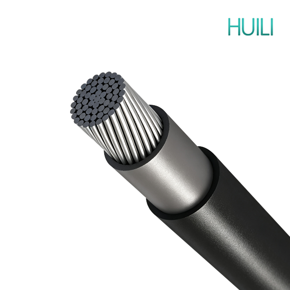
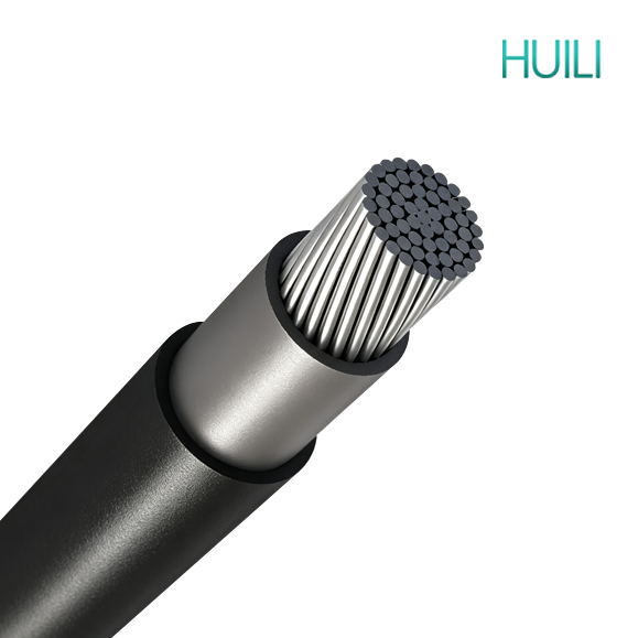
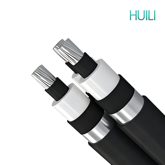
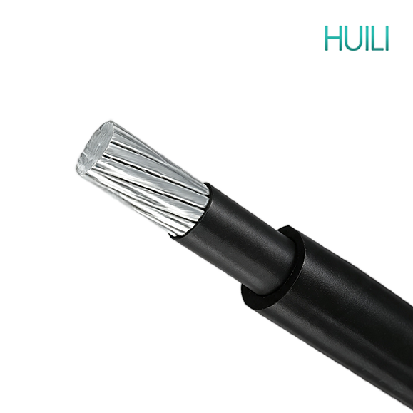
| Type CC & Type CCT 11kv 22kv 33kv Covered Conductor |
| Conductor size No./mm |
Conductor d.c. resistance at 20°C |
Conductor a.c. resistance at 80°C |
Reactance at 50 Hz (460 mm spacing) |
Continuous current carrying capacity |
Fault current rating kA for 1 sec.* |
Everday working tensionf kN |
Maximum working tension (50% MBL) kN |
Minimum breaking load kN |
Minimum bending radius mm |
| Based on 30°C ambient |
Based on 40°C ambient |
| Ω/km |
Ω/km |
Ω/km |
Still air |
1.0 m/s wind |
2.0 m/s wind |
|
|
|
| Alloy 6201 |
| 7/2.75 |
0.799 |
0.988 |
0.331 |
125 |
210 |
235 |
110 |
185 |
210 |
3.5 |
1.51 |
5.8 |
11.6 |
200 |
| 7/3.75 |
0.43 |
0.532 |
0.312 |
180 |
300 |
345 |
160 |
270 |
310 |
6.4 |
2.82 |
10.9 |
21.7 |
245 |
| 7/4.75 |
0.268 |
0.331 |
0.297 |
245 |
410 |
465 |
220 |
365 |
415 |
10.3 |
4.52 |
17.4 |
34.8 |
290 |
| 19/3.50 |
0.183 |
0.227 |
0.281 |
315 |
515 |
595 |
280 |
460 |
530 |
15.2 |
6.67 |
25.7 |
51.3 |
340 |
| Alloy 1120 |
| 7/2.75 |
0.713 |
0.881 |
0.331 |
130 |
220 |
250 |
115 |
195 |
225 |
3.7 |
1.49 |
4.96 |
9.91 |
200 |
| 7/3.75 |
0.383 |
0.474 |
0.312 |
190 |
320 |
365 |
170 |
285 |
325 |
6.8 |
2.64 |
8.8 |
17.6 |
245 |
| 7/4.75 |
0.239 |
0.296 |
0.297 |
260 |
430 |
485 |
230 |
385 |
435 |
11 |
4.07 |
13.6 |
27.1 |
290 |
| 19/3.50 |
0.163 |
0.202 |
0.281 |
330 |
545 |
625 |
295 |
485 |
560 |
16.2 |
6.26 |
20.9 |
41.7 |
340 |
| TECHNICAL PERFORMANCE CHARACTERISTICS FOR COVERED CONDUCTORS (CCT) |
| Conductor size No./mm |
Conductor d.c. resistance at 20°C |
Conductor a.c. resistance at 80°C |
Reactance at 50 Hz (460 mm spacing) |
Continuous current carrying capacity |
Fault current rating kA for 1 sec.* |
Everday working tensionf kN |
Maximum working tension (50% MBL) kN |
Minimum breaking load kN |
Minimum bending radius mm |
| Based on 30°C ambient |
Based on 40°C ambient |
| Ω/km |
Ω/km |
Ω/km |
Still air |
1.0 m/s wind |
2.0 m/s wind |
|
|
|
| 11 kv covered conductor Alloy 6201 |
| 7/3.75 |
0.43 |
0.532 |
0.312 |
185 |
295 |
330 |
165 |
265 |
295 |
6.4 |
2.82 |
10.9 |
21.7 |
285 |
| 7/4.75 |
0.268 |
0.331 |
0.297 |
245 |
390 |
440 |
220 |
350 |
395 |
10.3 |
4.52 |
17.4 |
34.8 |
330 |
| 19/3.50 |
0.183 |
0.227 |
0.281 |
315 |
500 |
560 |
280 |
445 |
500 |
15.2 |
6.67 |
25.7 |
51.3 |
380 |
| 22 kV covered conductor Alloy 6201 |
| 7/3.75 |
0.43 |
0.532 |
0.312 |
185 |
285 |
315 |
165 |
255 |
280 |
6.4 |
2.82 |
10.9 |
21.7 |
350 |
| 7/4.75 |
0.268 |
0.331 |
0.297 |
245 |
375 |
420 |
220 |
335 |
375 |
10.3 |
4.52 |
17.4 |
34.8 |
395 |
| 19/3.50 |
0.183 |
0.227 |
0.281 |
315 |
475 |
530 |
280 |
425 |
475 |
15.2 |
6.67 |
25.7 |
51.3 |
445 |
| 33kv covered conductor Alloy 6201 |
| 7/3.75 |
0.43 |
0.532 |
0.312 |
185 |
270 |
295 |
165 |
240 |
265 |
6.4 |
2.82 |
10.9 |
21.7 |
425 |
| 7/4.75 |
0.268 |
0.331 |
0.297 |
245 |
360 |
400 |
220 |
320 |
355 |
10.3 |
4.52 |
17.4 |
34.8 |
470 |
| 19/3.50 |
0.183 |
0.227 |
0.281 |
315 |
455 |
505 |
280 |
405 |
450 |
15.2 |
6.67 |
25.7 |
51.3 |
520 |
| XLPE covered aerial cables Alloy 1120 conductors |
| Conductor size No./mm |
Conductor d.c. resistance at 20°C |
Conductor a.c. resistance at 80°C |
Reactance at 50 Hz (460 mm spacing) |
Continuous current carrying capacity |
Fault current rating kA for 1 sec.* |
Everday working tensionf kN |
Maximum working tension (50% MBL) kN |
Minimum breaking load kN |
Minimum bending radius mm |
| Based on 30°C ambient |
Based on 40°C ambient |
| Ω/km |
Ω/km |
Ω/km |
Still air |
1.0 m/s wind |
2.0 m/s wind |
|
|
|
| 11kv covered conductor Alloy 1120 |
| 7/2.75 |
0.713 |
0.881 |
0.331 |
130 |
215 |
240 |
115 |
190 |
215 |
3.7 |
1.49 |
4.96 |
9.9 |
230 |
| 7/3.75 |
0.383 |
0.474 |
0.312 |
190 |
315 |
345 |
170 |
280 |
310 |
6.8 |
2.64 |
8.8 |
17.6 |
285 |
| 7/4.75 |
0.239 |
0.296 |
0.297 |
26() |
415 |
470 |
230 |
370 |
420 |
11 |
4.07 |
13.6 |
27.1 |
330 |
| 19/3.50 |
0.163 |
0.202 |
0.281 |
330 |
525 |
595 |
295 |
470 |
530 |
16.2 |
6.26 |
20.9 |
41.7 |
380 |
| 22 kV covered conductor Alloy 1120 |
| 7/2.75 |
0.713 |
0.881 |
0.331 |
135 |
205 |
225 |
120 |
185 |
200 |
3.7 |
1.49 |
4.96 |
9.9 |
300 |
| 7/3.75 |
0.383 |
0.474 |
0.312 |
190 |
295 |
330 |
170 |
265 |
295 |
6.8 |
2.64 |
8.8 |
17.6 |
350 |
| 7/4.75 |
0.239 |
0.296 |
0.297 |
260 |
400 |
440 |
230 |
355 |
395 |
11 |
4.07 |
13.6 |
27.1 |
395 |
| 19/3.50 |
0.163 |
0.202 |
0.281 |
330 |
505 |
560 |
295 |
450 |
500 |
16.2 |
6.26 |
20.9 |
41.7 |
445 |
| 33kv covered conductor Alloy 1120 |
| 7/2.75 |
0.713 |
0.881 |
0.331 |
135 |
195 |
215 |
120 |
175 |
190 |
3.7 |
1.49 |
4.96 |
9.9 |
385 |
| 7/3.75 |
0.383 |
0.474 |
0.312 |
195 |
285 |
315 |
175 |
255 |
280 |
6.8 |
2.64 |
8.8 |
17.6 |
425 |
| 7/4.75 |
0.239 |
0.296 |
0.297 |
260 |
380 |
420 |
230 |
340 |
375 |
11 |
4.07 |
13.6 |
27.1 |
470 |
| 19/3.50 |
0.163 |
0.202 |
0.281 |
330 |
480 |
530 |
295 |
430 |
475 |
16.2 |
6.26 |
20.9 |
41.7 |
520 |
| * Initial temperature 80°C, final temperature 210°C, constant K = 83.0 for alloy 6201 and 88.4 for alloy 1120. f 13% MBL fbr alloy 6201 and 15% MBL for alloy 1120. |